D. Vent Diagrams
Note: The 6000 series fireplaces can adapt to SL series vent pipe, if desired.
When venting off the top of the unit, use a
After the 48 inch vertical section, the venting table rules must be followed. The first 48 inch vertical section is NOT counted as part of the vertical components in the table. It is still counted as part of the overall maximum run. All venting table rules for the vent run must still be followed.
Example: DVP pipe 3 ft. min. vertical = 11 ft. max. horizontal SL pipe 7 ft. min. vertical = 11 ft. max. horizontal
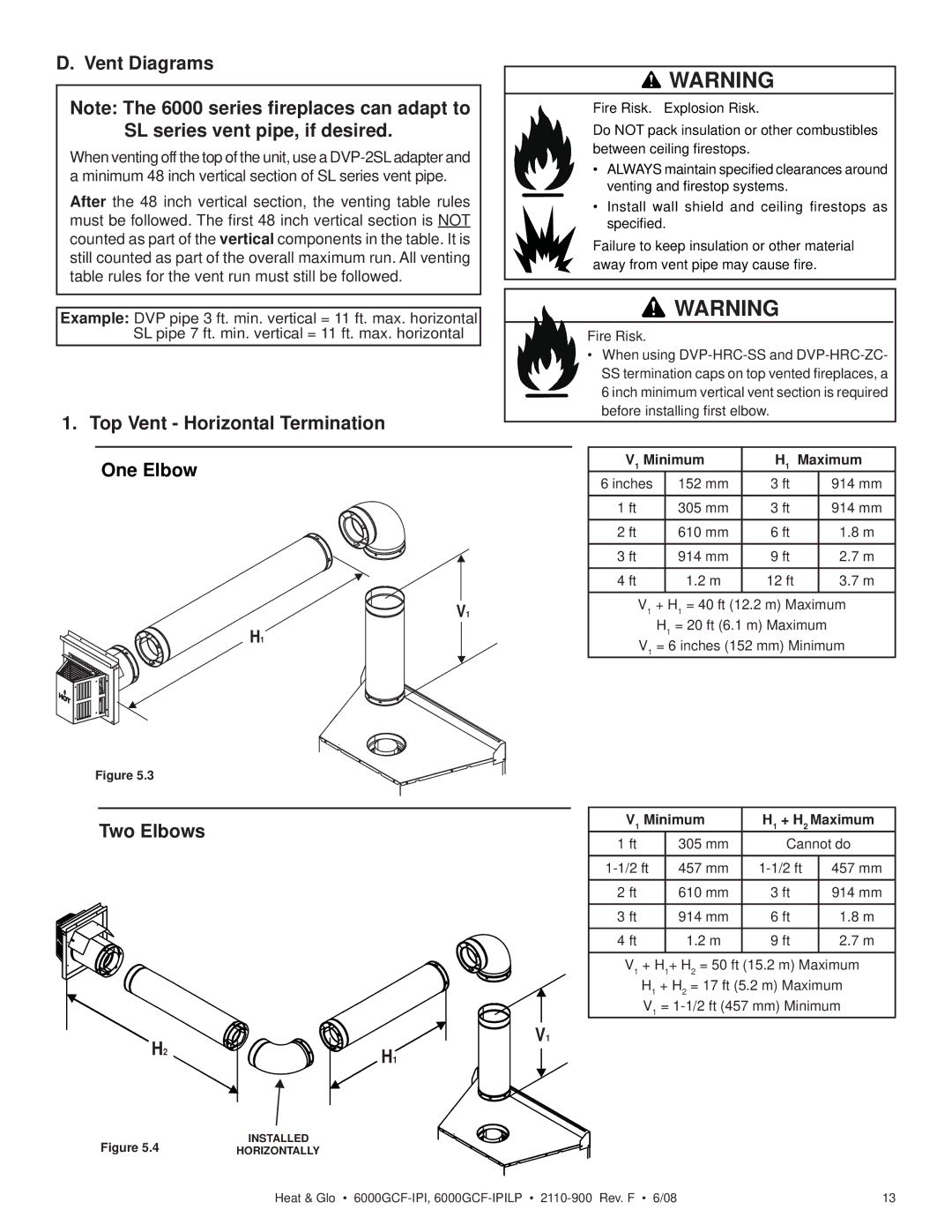
1.Top Vent - Horizontal Termination One Elbow
V1
H1
Figure 5.3
![]() WARNING
WARNING
Fire Risk. Explosion Risk.
Do NOT pack insulation or other combustibles between ceiling firestops.
•ALWAYS maintain specified clearances around venting and firestop systems.
•Install wall shield and ceiling firestops as specified.
Failure to keep insulation or other material away from vent pipe may cause fire.
WARNING
Fire Risk.
•When using
V1 Minimum | H1 | Maximum | ||
6 inches | 152 mm | 3 ft |
| 914 mm |
1 ft | 305 mm | 3 ft |
| 914 mm |
|
|
|
|
|
2 ft | 610 mm | 6 ft |
| 1.8 m |
|
|
|
|
|
3 ft | 914 mm | 9 ft |
| 2.7 m |
4 ft | 1.2 m | 12 ft |
| 3.7 m |
V1 + H1 = 40 ft (12.2 m) Maximum
H1 = 20 ft (6.1 m) Maximum
V1 = 6 inches (152 mm) Minimum
Two Elbows
H2H1
V1
V1 Minimum | H1 + H2 Maximum | ||
1 ft | 305 mm | Cannot do | |
|
|
|
|
457 mm | 457 mm | ||
|
|
|
|
2 ft | 610 mm | 3 ft | 914 mm |
3 ft | 914 mm | 6 ft | 1.8 m |
4 ft | 1.2 m | 9 ft | 2.7 m |
|
|
|
|
V1 + H1+ H2 = 50 ft (15.2 m) Maximum
H1 + H2 = 17 ft (5.2 m) Maximum V1 =
Figure 5.4 | INSTALLED |
HORIZONTALLY |
Heat & Glo • | 13 |