6 Vent Clearances and Framing
A. Pipe Clearances to Combustibles
![]() WARNING
WARNING
Fire Risk. Explosion Risk.
Maintain vent clearance to combustibles as specified.
•Do not pack air space with insulation or other materials.
Failure to keep insulation or other materials away from vent pipe may cause fire.
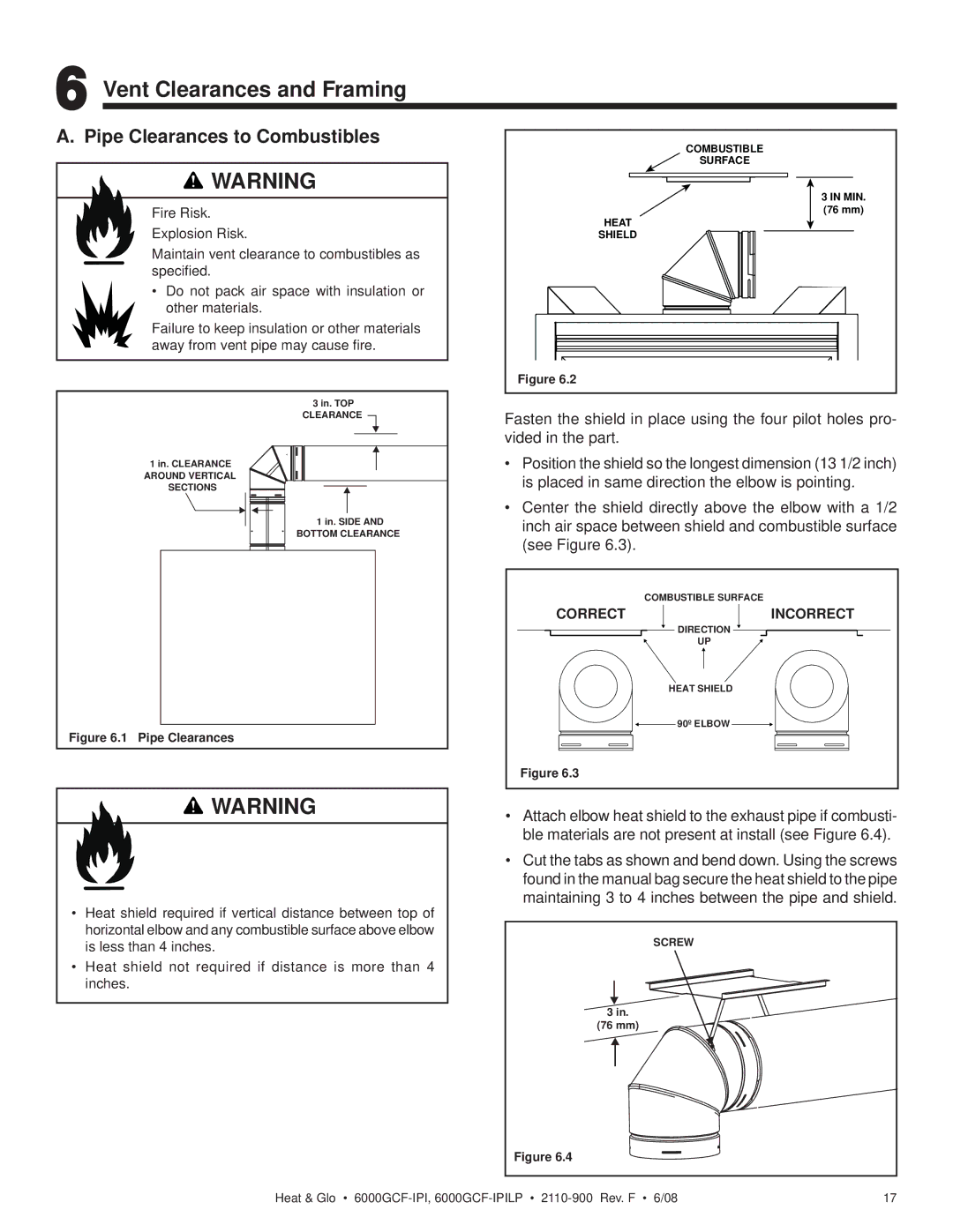
3 in. TOP CLEARANCE
1 in. CLEARANCE AROUND VERTICAL SECTIONS
1 in. SIDE AND BOTTOM CLEARANCE
Figure 6.1 Pipe Clearances
![]() WARNING
WARNING
Fire Risk.
Installation of this appliance may require the use of heat shield
•Heat shield required if vertical distance between top of horizontal elbow and any combustible surface above elbow is less than 4 inches.
•Heat shield not required if distance is more than 4 inches.
COMBUSTIBLE |
SURFACE |
3 IN MIN. |
(76 mm) |
HEAT |
SHIELD |
Figure 6.2 |
Fasten the shield in place using the four pilot holes pro- vided in the part.
•Position the shield so the longest dimension (13 1/2 inch) is placed in same direction the elbow is pointing.
•Center the shield directly above the elbow with a 1/2 inch air space between shield and combustible surface (see Figure 6.3).
| COMBUSTIBLE SURFACE |
CORRECT | INCORRECT |
| DIRECTION |
| UP |
| HEAT SHIELD |
| 90º ELBOW |
Figure 6.3 |
|
•Attach elbow heat shield to the exhaust pipe if combusti- ble materials are not present at install (see Figure 6.4).
•Cut the tabs as shown and bend down. Using the screws found in the manual bag secure the heat shield to the pipe maintaining 3 to 4 inches between the pipe and shield.
SCREW
3in.
(76 mm)
Figure 6.4
Heat & Glo • | 17 |