3 Framing and Clearances
Note:
•Illustrations reflect typical installations and are FOR DESIGN PURPOSES ONLY.
•Illustrations/diagrams are not drawn to scale.
•Actual installation may vary due to individual design preference.
A.Selecting Appliance Location
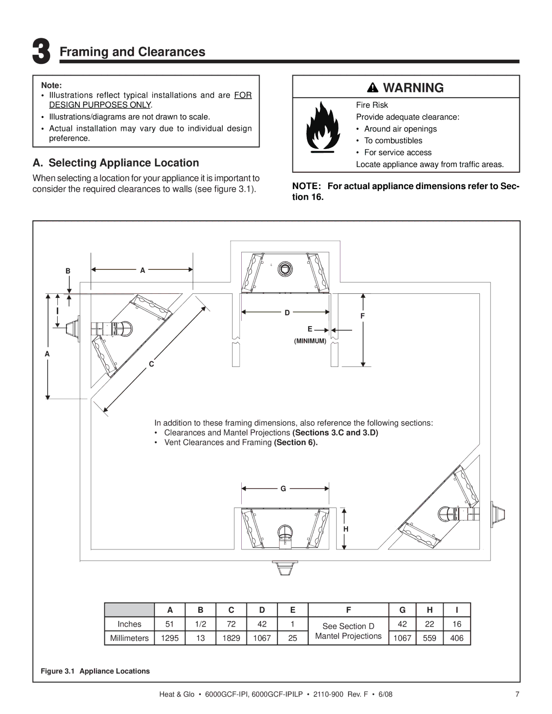
When selecting a location for your appliance it is important to consider the required clearances to walls (see figure 3.1).
![]() WARNING
WARNING
Fire Risk
Provide adequate clearance:
•Around air openings
•To combustibles
• For service access
Locate appliance away from traffic areas.
NOTE: For actual appliance dimensions refer to Sec- tion 16.
B
I
A
A
D | F |
|
E
(MINIMUM)
C
In addition to these framing dimensions, also reference the following sections:
•Clearances and Mantel Projections (Sections 3.C and 3.D)
•Vent Clearances and Framing (Section 6).
G
H
| A | B | C | D | E | F | G | H | I |
Inches | 51 | 1/2 | 72 | 42 | 1 | See Section D | 42 | 22 | 16 |
Millimeters | 1295 | 13 | 1829 | 1067 | 25 | Mantel Projections | 1067 | 559 | 406 |
Figure 3.1 Appliance Locations
Heat & Glo • | 7 |