2.Match the amount of vertical in the system with the chart to find the appropriate position to set the Flue Restrictor (see Figure 7.7).
- CHART -
Vertical | Top Vent | Top Vent | |
NG | LP | ||
| |||
4’ | No Restrictor | ||
|
|
| |
8’ | |||
|
|
| |
15’ | |||
20’ | |||
25’ | |||
|
|
| |
30’ | |||
35’ | |||
40’ | |||
|
|
| |
45’ | |||
|
|
| |
50’ |
Figure 7.7
3. Center the Flue Restrictor on vent and secure in place by using two
1 2 3 4 5
SETTING
1 2 3 4 5
Figure 7.8
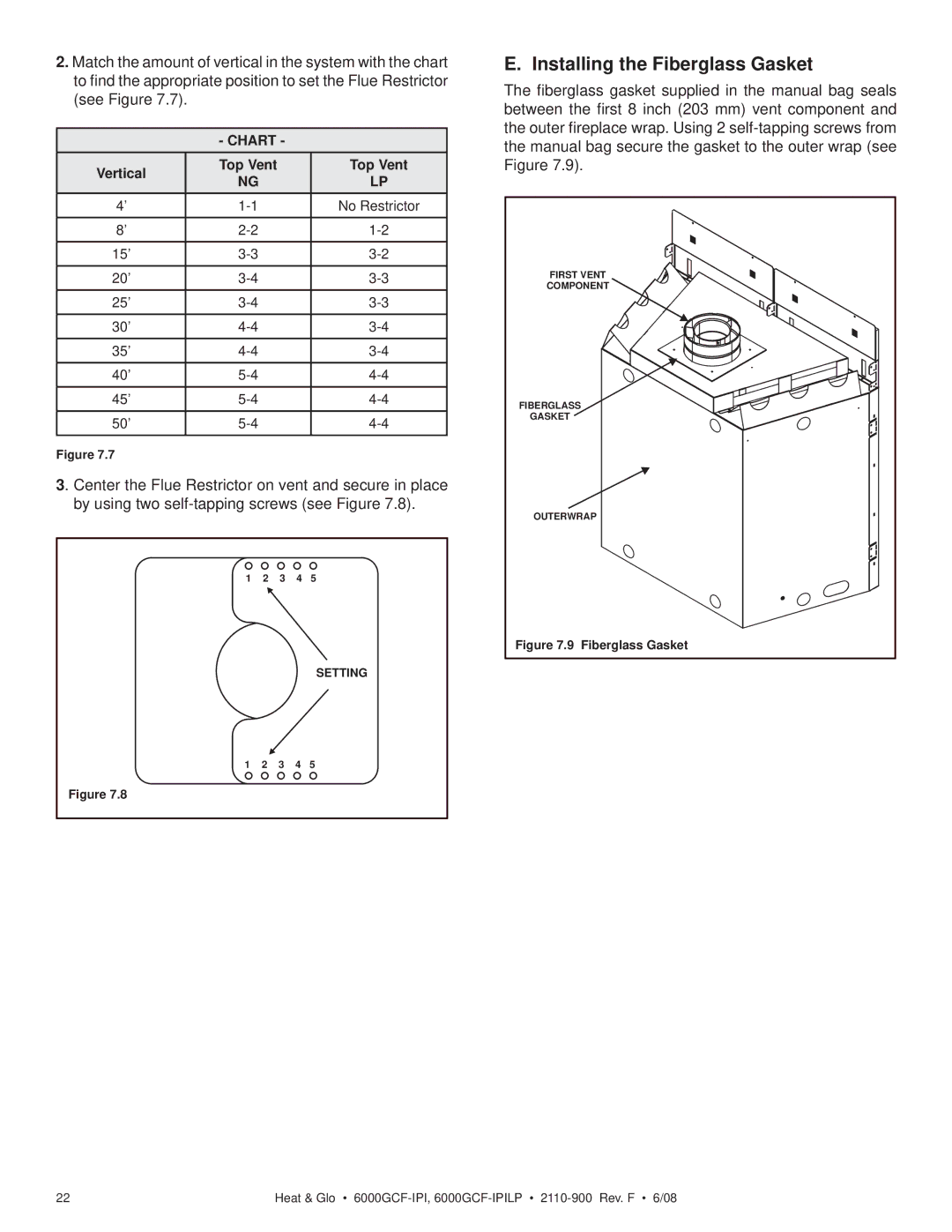
E. Installing the Fiberglass Gasket
The fiberglass gasket supplied in the manual bag seals between the first 8 inch (203 mm) vent component and the outer fireplace wrap. Using 2
FIRST VENT |
COMPONENT |
FIBERGLASS |
GASKET |
OUTERWRAP |
Figure 7.9 Fiberglass Gasket |
22 | Heat & Glo • |