RED60 2159-900 specifications
The Heat & Glo LifeStyle RED60 2159-900 is a modern and innovative gas fireplace that exemplifies cutting-edge design and advanced heating technology. With its sleek aesthetics and smart features, this fireplace is designed to elevate both comfort and style in any living space.One of the main features of the RED60 is its impressive heat output. This model boasts a high efficiency rating, ensuring that homeowners can enjoy warmth without excessive energy consumption. The fireplace can deliver an output of up to 60,000 BTUs, making it suitable for both large and small areas. This efficient performance means less environmental impact, aligning with the growing emphasis on sustainability in home heating solutions.
The design of the Heat & Glo LifeStyle RED60 is another standout aspect. Its expansive glass viewing area provides a panoramic view of the flames, creating a beautiful focal point in any room. The minimalist frame enhances the contemporary aesthetic, allowing it to seamlessly complement various interior styles, from modern chic to traditional elegance.
In terms of technology, the RED60 incorporates advanced combustion systems, ensuring cleaner emissions without sacrificing performance. This technology not only contributes to a healthier indoor environment but also helps reduce the carbon footprint associated with home heating. Additionally, the fireplace features a patented heat distribution system, which optimally circulates warmth throughout the space, eliminating cold spots and enhancing overall comfort.
The RED60 also offers convenience through its intuitive remote control system. Users can easily adjust the flame height, heat output, and even set timers, providing ultimate flexibility in managing their indoor climate. For those who prefer a more hands-on approach, manual controls are also available, making it user-friendly for everyone.
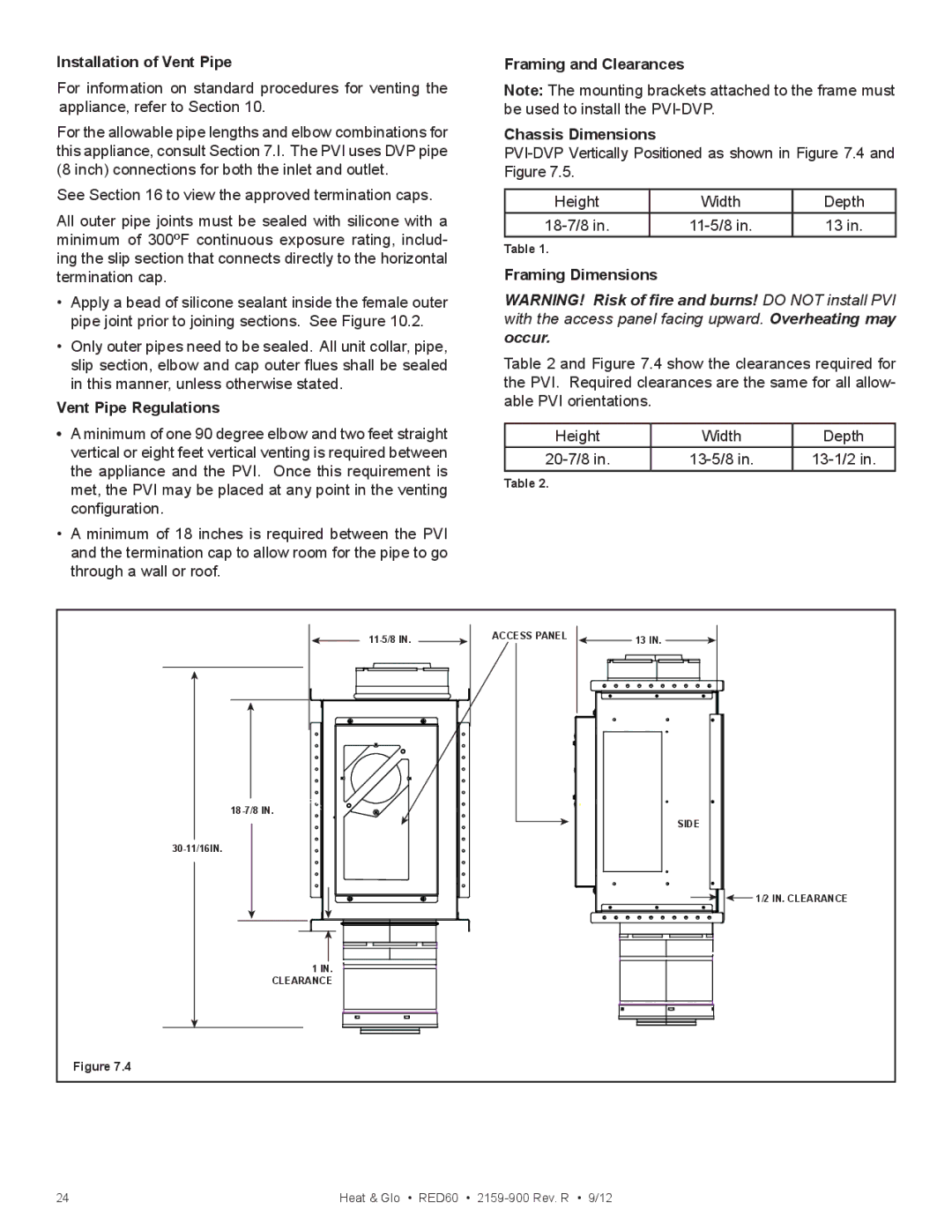
Moreover, the installation process is simplified with the unit's flexible venting options, which can accommodate various configurations to suit different homes. Whether designing for a new build or retrofitting an existing space, this versatility appeals to homeowners and builders alike.
In summary, the Heat & Glo LifeStyle RED60 2159-900 is a blend of style, efficiency, and advanced technology. Its high heat output, sleek design, and intuitive controls make it an excellent choice for anyone seeking to enhance their living environment with a modern gas fireplace.

