|
| Cylinder Control Valve Installation | |
Control | Handle Assembly Installation : | ||
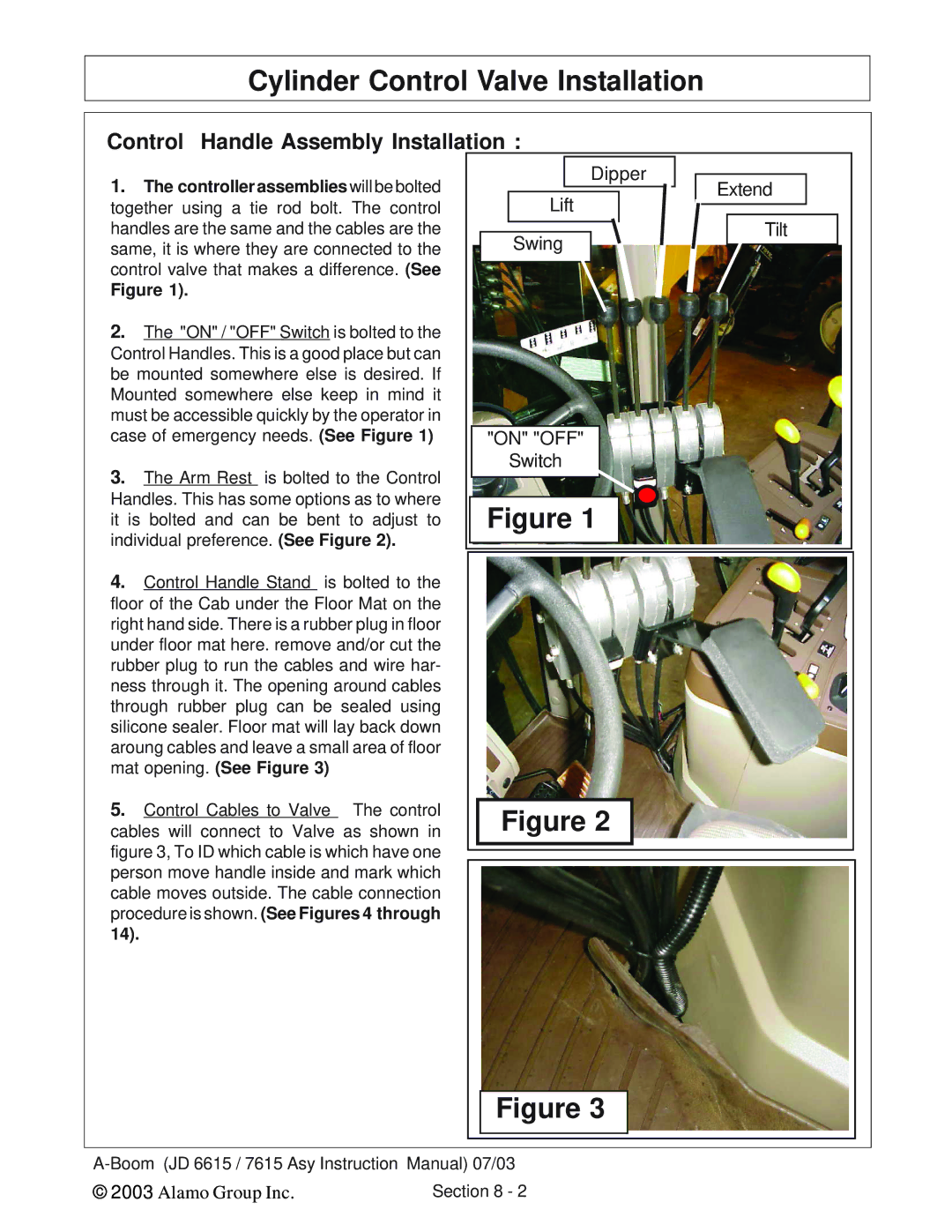
1. | The controller assemblies will be bolted | Dipper | |
Extend | |||
together using a tie rod bolt. The control | Lift | ||
handles are the same and the cables are the | Tilt | ||
same, it is where they are connected to the | Swing | ||
control valve that makes a difference. (See |
| ||
Figure 1). |
|
| |
2. | The "ON" / "OFF" Switch is bolted to the |
| |
Control Handles. This is a good place but can |
| ||
be mounted somewhere else is desired. If |
| ||
Mounted somewhere else keep in mind it |
| ||
must be accessible quickly by the operator in |
| ||
case of emergency needs. (See Figure 1) | "ON" "OFF" | ||
3. | The Arm Rest is bolted to the Control | Switch | |
| |||
Handles. This has some options as to where | Figure 1 | ||
it is bolted and can be bent to adjust to | |||
individual preference. (See Figure 2). |
| ||
4.Control Handle Stand is bolted to the floor of the Cab under the Floor Mat on the right hand side. There is a rubber plug in floor under floor mat here. remove and/or cut the rubber plug to run the cables and wire har- ness through it. The opening around cables through rubber plug can be sealed using silicone sealer. Floor mat will lay back down aroung cables and leave a small area of floor mat opening. (See Figure 3)
5. Control Cables to Valve The control cables will connect to Valve as shown in figure 3, To ID which cable is which have one person move handle inside and mark which cable moves outside. The cable connection procedure is shown. (See Figures 4 through 14).
Figure 2
Figure 3
© 2003 Alamo Group Inc. | Section 8 - 2 |
