Hyd. Tank - CWT Installation
Hydraulic Tank Installation:
1.Caution. Care must be taken to keep Hydrau- lic System clean. Do not leave any openings in Tank while installing it, they must remain sealed untill ready to install a component and then sealed back up.
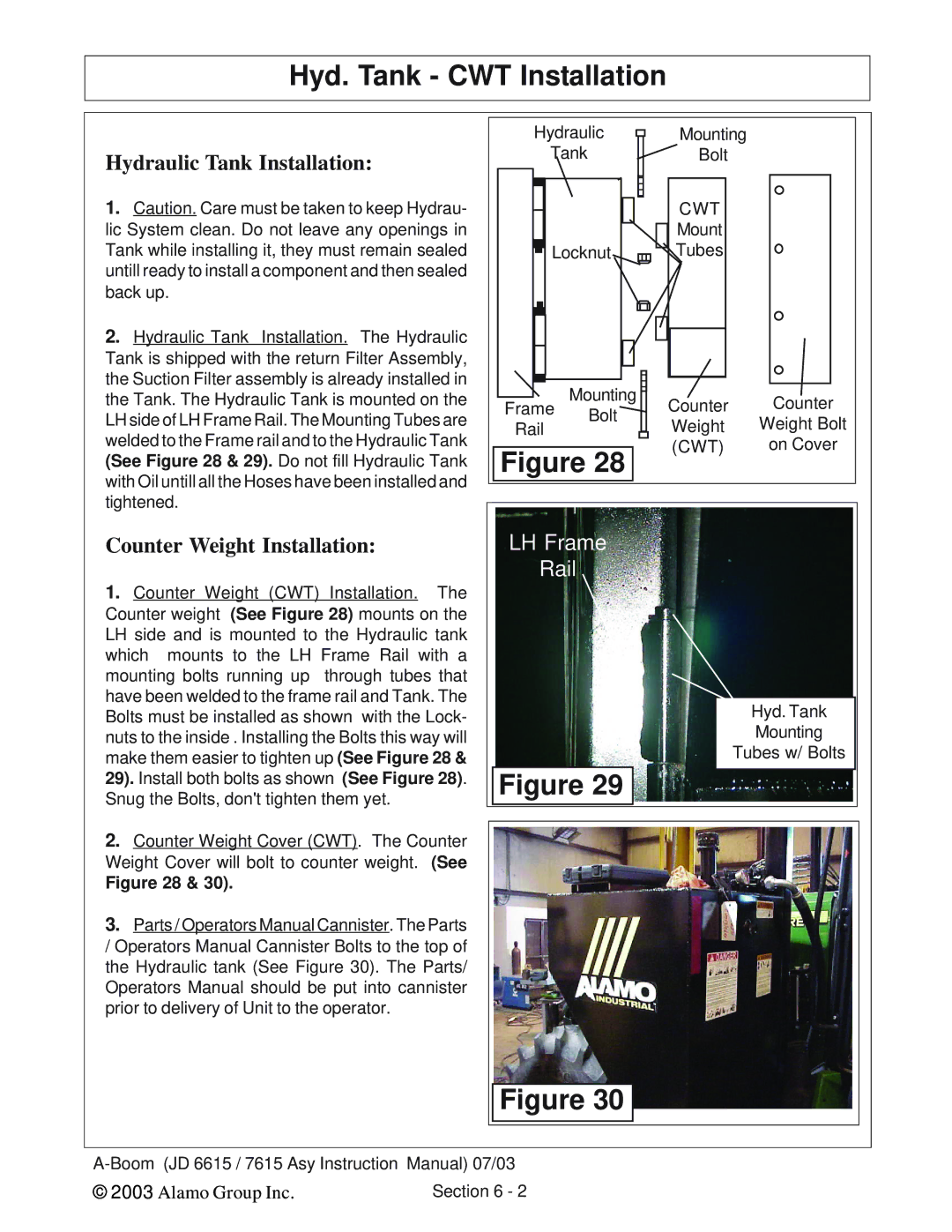
2.Hydraulic Tank Installation. The Hydraulic Tank is shipped with the return Filter Assembly, the Suction Filter assembly is already installed in the Tank. The Hydraulic Tank is mounted on the LH side of LH Frame Rail. The Mounting Tubes are welded to the Frame rail and to the Hydraulic Tank (See Figure 28 & 29). Do not fill Hydraulic Tank with Oil untill all the Hoses have been installed and tightened.
Counter Weight Installation:
1.Counter Weight (CWT) Installation. The Counter weight (See Figure 28) mounts on the LH side and is mounted to the Hydraulic tank which mounts to the LH Frame Rail with a mounting bolts running up through tubes that have been welded to the frame rail and Tank. The Bolts must be installed as shown with the Lock- nuts to the inside . Installing the Bolts this way will make them easier to tighten up (See Figure 28 & 29). Install both bolts as shown (See Figure 28). Snug the Bolts, don't tighten them yet.
Hydraulic | Mounting |
Tank | Bolt |
|
| CWT |
| |
|
| Mount |
| |
Locknut | Tubes |
| ||
Frame | Mounting | Counter | Counter | |
Bolt | ||||
Rail | Weight | Weight Bolt | ||
| ||||
Figure 28 | (CWT) | on Cover | ||
|
| |||
LH Frame |
|
| ||
Rail |
|
| ||
|
|
| Hyd. Tank | |
|
|
| Mounting | |
|
|
| Tubes w/ Bolts | |
Figure 29 |
|
| ||
2.Counter Weight Cover (CWT). The Counter Weight Cover will bolt to counter weight. (See
Figure 28 & 30).
3.Parts / Operators Manual Cannister. The Parts / Operators Manual Cannister Bolts to the top of the Hydraulic tank (See Figure 30). The Parts/ Operators Manual should be put into cannister prior to delivery of Unit to the operator.
Figure 30
© 2003 Alamo Group Inc. | Section 6 - 2 |