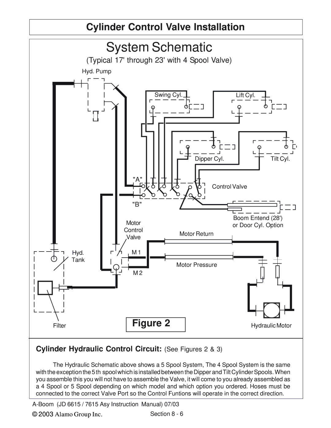
Cylinder Control Valve Installation
System Schematic
(Typical 17' through 23' with 4 Spool Valve)
Hyd. Pump
Swing Cyl.
Lift Cyl.
Dipper Cyl. | Tilt Cyl. |
"A" |
|
Control Valve |
|
"B" |
|
Hyd. Tank
Motor
Control
Valve
M 1 |
M 2 |
Motor Return
Motor Pressure
Boom Entend (28') or Door Cyl. Option
Filter
Figure 2
Hydraulic Motor
Cylinder Hydraulic Control Circuit: (See Figures 2 & 3)
The Hydraulic Schematic above shows a 5 Spool System, The 4 Spool System is the same with the exception the 5 th spool which is installed between the Dipper and Tilt Cylinder Spools. When you assemble this you will not have to assemble the Valve, it will come to you already assembled as a 4 Spool or 5 Spool depending on which model and which option you ordered. Hoses must be connected to the correct Valve Port so the Control Funtions will operate in the correct direction.
© 2003 Alamo Group Inc. | Section 8 - 6 |