Boom Installation
Cutter Motor Control Valve Asy:
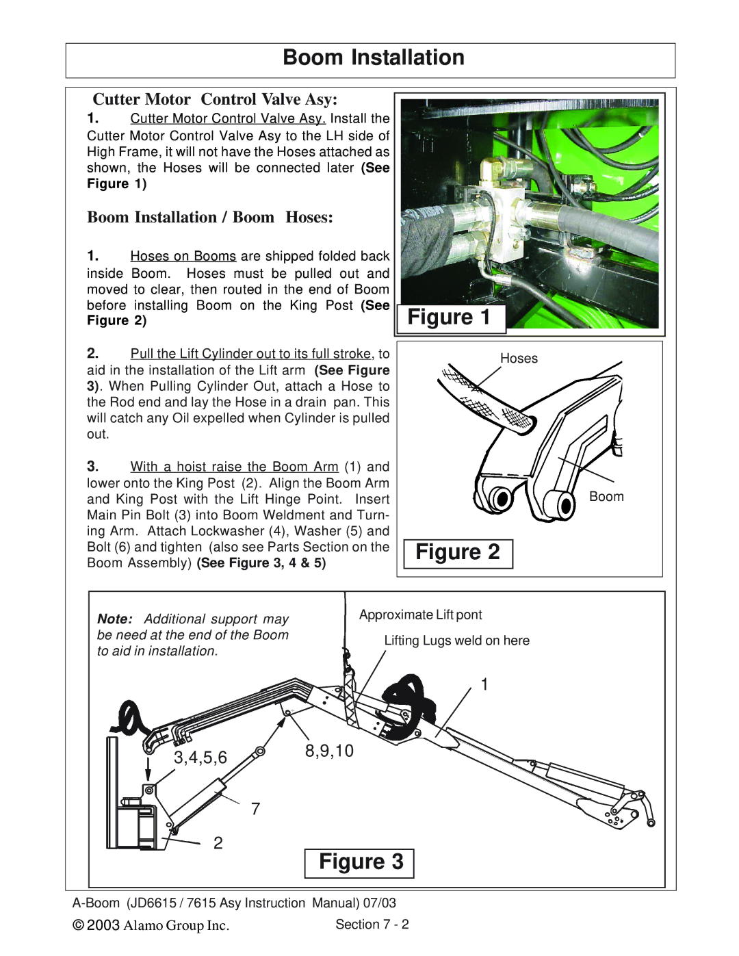
1.Cutter Motor Control Valve Asy. Install the Cutter Motor Control Valve Asy to the LH side of High Frame, it will not have the Hoses attached as shown, the Hoses will be connected later (See
Figure 1)
Boom Installation / Boom Hoses:
1.Hoses on Booms are shipped folded back inside Boom. Hoses must be pulled out and moved to clear, then routed in the end of Boom before installing Boom on the King Post (See
Figure 2)
2.Pull the Lift Cylinder out to its full stroke, to aid in the installation of the Lift arm (See Figure 3). When Pulling Cylinder Out, attach a Hose to the Rod end and lay the Hose in a drain pan. This will catch any Oil expelled when Cylinder is pulled out.
3. With a hoist raise the Boom Arm (1) and lower onto the King Post (2). Align the Boom Arm and King Post with the Lift Hinge Point. Insert Main Pin Bolt (3) into Boom Weldment and Turn- ing Arm. Attach Lockwasher (4), Washer (5) and Bolt (6) and tighten (also see Parts Section on the Boom Assembly) (See Figure 3, 4 & 5)
Figure 1
Hoses
Boom
Figure 2
Note: Additional support may be need at the end of the Boom to aid in installation.
3,4,5,6
7
2
Approximate Lift pont
Lifting Lugs weld on here
1
8,9,10
Figure 3
© 2003 Alamo Group Inc. | Section 7 - 2 |