Pump / Drive Assembly Instructions
Installing Pump Mount Plate & Tube End of Driveshaft: (continued)
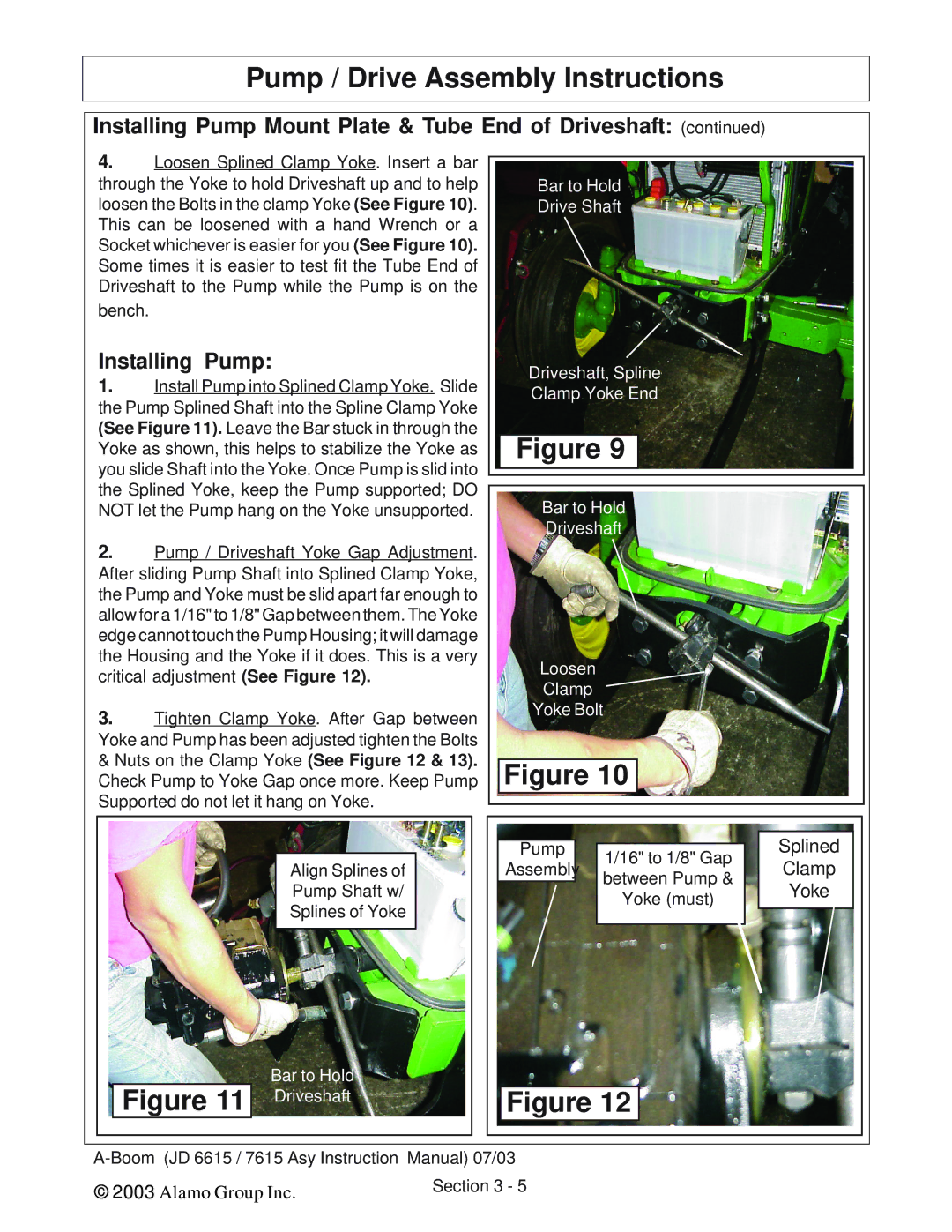
4.Loosen Splined Clamp Yoke. Insert a bar through the Yoke to hold Driveshaft up and to help loosen the Bolts in the clamp Yoke (See Figure 10). This can be loosened with a hand Wrench or a Socket whichever is easier for you (See Figure 10). Some times it is easier to test fit the Tube End of Driveshaft to the Pump while the Pump is on the bench.
Installing Pump:
1.Install Pump into Splined Clamp Yoke. Slide the Pump Splined Shaft into the Spline Clamp Yoke (See Figure 11). Leave the Bar stuck in through the Yoke as shown, this helps to stabilize the Yoke as you slide Shaft into the Yoke. Once Pump is slid into the Splined Yoke, keep the Pump supported; DO NOT let the Pump hang on the Yoke unsupported.
2.Pump / Driveshaft Yoke Gap Adjustment. After sliding Pump Shaft into Splined Clamp Yoke, the Pump and Yoke must be slid apart far enough to allow for a 1/16" to 1/8" Gap between them. The Yoke edge cannot touch the Pump Housing; it will damage the Housing and the Yoke if it does. This is a very critical adjustment (See Figure 12).
3.Tighten Clamp Yoke. After Gap between Yoke and Pump has been adjusted tighten the Bolts & Nuts on the Clamp Yoke (See Figure 12 & 13). Check Pump to Yoke Gap once more. Keep Pump Supported do not let it hang on Yoke.
Align Splines of
Pump Shaft w/
Splines of Yoke
Bar to Hold
Figure 11 Driveshaft
Bar to Hold
Drive Shaft
Driveshaft, Spline
Clamp Yoke End
Figure 9
Bar to Hold
Driveshaft
Loosen
Clamp
Yoke Bolt
Figure 10
Pump | 1/16" to 1/8" Gap | Splined | |
Assembly | Clamp | ||
between Pump & | |||
| Yoke | ||
| Yoke (must) | ||
|
| ||
Figure 12 |
| ||
© 2003 | Alamo Group Inc. | Section 3 - 5 |
|