Pump / Drive Assembly Instructions
Installing Pump: (continued)
5. Mount Pump to Pump Plate. Remove the Bar that is slid through the Driveshaft Yoke and push the Pump inward (See Figure 14). This will make the two piece Driveshaft slide together al- lowing the Pump to be pushed towards the tractor. Do this untill the Pump is against the Pump Plate
(See Figure 15).
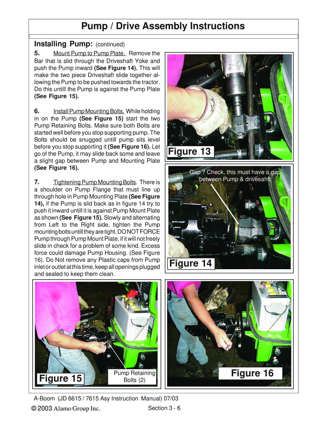
6.Install Pump Mounting Bolts. While holding in on the Pump (See Figure 15) start the two Pump Retaining Bolts. Make sure both Bolts are started well before you stop supporting pump. The Bolts should be snugged untill pump sits level before you stop supporting it (See Figure 16). Let go of the Pump, it may slide back some and leave a slight gap between Pump and Mounting Plate
(See Figure 16).
7.Tightening Pump Mounting Bolts. There is a shoulder on Pump Flange that must line up through hole in Pump Mounting Plate (See Figure 14), if the Pump is slid back as in figure 14 try to push it inward untill it is against Pump Mount Plate as shown (See Figure 15). Slowly and alternating from Left to the Right side, tighten the Pump mounting bolts untill they are tight. DO NOT FORCE Pump through Pump Mount Plate, if it will not freely slide in check for a problem of some kind. Excess force could damage Pump Housing. (See Figure 16). Do Not remove any Plastic caps from Pump inlet or outlet at this time, keep all openings plugged and sealed to keep them clean.
Figure 13
Gap ? Check, this must have a gap
between Pump & drivesahft
Figure 14
Figure 15 | Pump Retaining | Figure 16 |
Bolts (2) |
| |
| ||
© 2003 Alamo Group Inc. | Section 3 - 6 |
|