Frame Rail Installation 4 WD
Re-Install High Frame to Tractor: (continued)
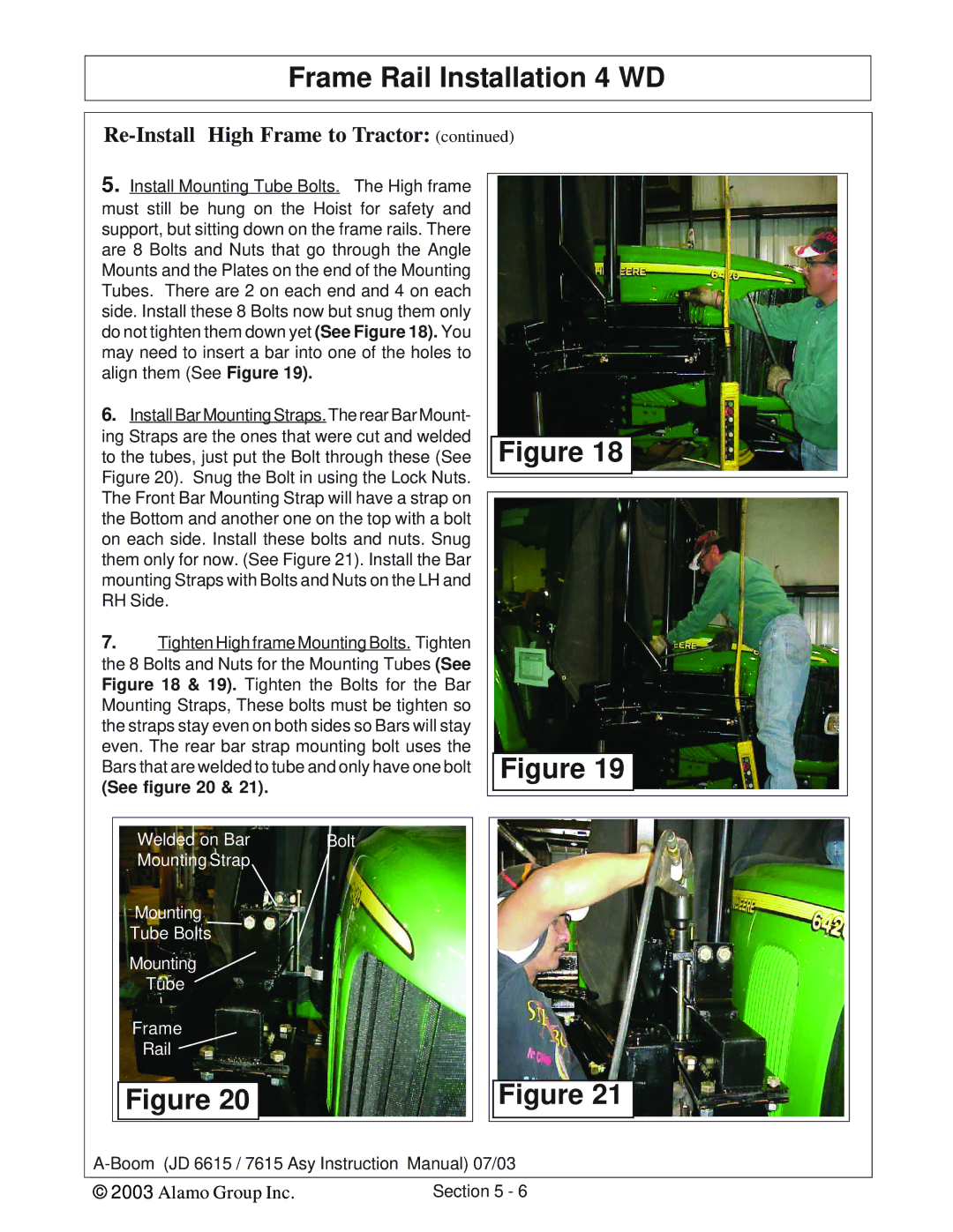
5.Install Mounting Tube Bolts. The High frame must still be hung on the Hoist for safety and support, but sitting down on the frame rails. There are 8 Bolts and Nuts that go through the Angle Mounts and the Plates on the end of the Mounting Tubes. There are 2 on each end and 4 on each side. Install these 8 Bolts now but snug them only do not tighten them down yet (See Figure 18). You may need to insert a bar into one of the holes to align them (See Figure 19).
6.Install Bar Mounting Straps. The rear Bar Mount- ing Straps are the ones that were cut and welded to the tubes, just put the Bolt through these (See Figure 20). Snug the Bolt in using the Lock Nuts. The Front Bar Mounting Strap will have a strap on the Bottom and another one on the top with a bolt on each side. Install these bolts and nuts. Snug them only for now. (See Figure 21). Install the Bar mounting Straps with Bolts and Nuts on the LH and RH Side.
7.Tighten High frame Mounting Bolts. Tighten the 8 Bolts and Nuts for the Mounting Tubes (See Figure 18 & 19). Tighten the Bolts for the Bar Mounting Straps, These bolts must be tighten so the straps stay even on both sides so Bars will stay even. The rear bar strap mounting bolt uses the Bars that are welded to tube and only have one bolt
(See figure 20 & 21).
Figure 18
Figure 19
Welded on Bar | Bolt |
Mounting Strap |
|
Mounting
Tube Bolts
Mounting
Tube
Frame
Rail
Figure 20
Figure 21
© 2003 Alamo Group Inc. | Section 5 - 6 |