3Installing the Appliance
Constructing the Appliance Chase
A chase is a vertical
CAUTION: TREATMENT OF FIRESTOP SPACERS AND CONSTRUCTION OF THE CHASE MAY VARY WITH THE TYPE OF BUILDING. THESE INSTRUCTIONS ARE NOT SUBSTITUTES FOR THE REQUIREMENTS OF LOCAL BUILDING CODES. THEREFORE, YOUR LOCAL BUILD- ING CODES MUST BE CHECKED TO DETERMINE THE REQUIREMENTS FOR THESE STEPS.
This means that the walls, ceiling, base plate and cantilever floor of the chase should be insulated. Vapor and air infiltra- tion barriers should be installed in the chase as per regional codes for the rest of the home. Additionally, in regions where cold air infiltration may be an issue, the inside surfaces may be sheetrocked and taped for maximum air tightness.
To further prevent drafts, the firestops should be caulked to seal gaps. Gas line holes and other openings should be caulked or stuffed with insulation. If the unit is being in- stalled on a cement slab, a layer of plywood may be placed underneath to prevent conducting cold up into the room.
THE CHASE SHOULD BE CONSTRUCTED SO THAT ALL CLEARANCES TO THE APPLIANCE ARE MAINTAINED AS SPECIFIED WITHIN THIS INSTALLERS GUIDE.
Step 1. Locating the Appliance
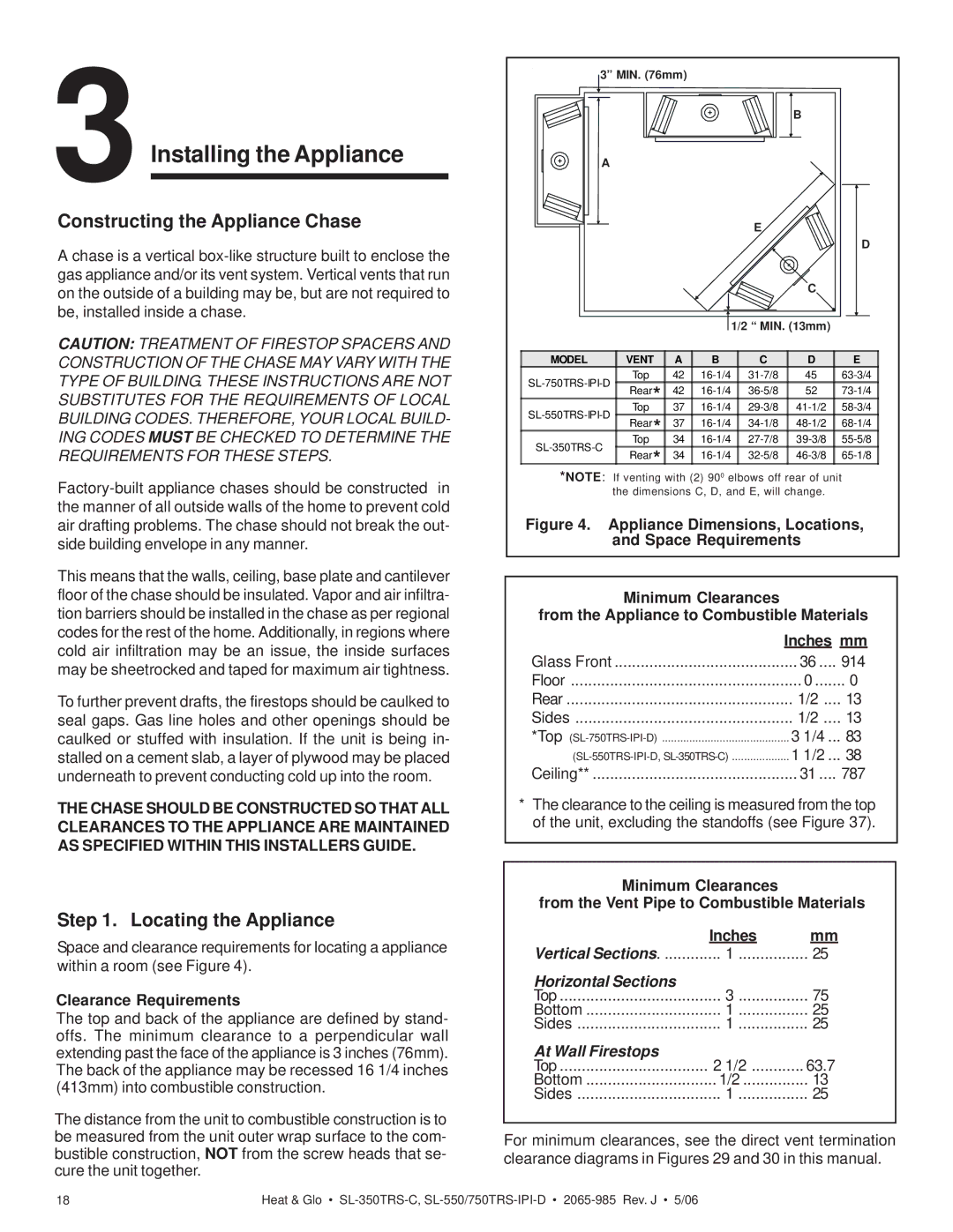
Space and clearance requirements for locating a appliance within a room (see Figure 4).
Clearance Requirements
The top and back of the appliance are defined by stand- offs. The minimum clearance to a perpendicular wall extending past the face of the appliance is 3 inches (76mm). The back of the appliance may be recessed 16 1/4 inches (413mm) into combustible construction.
The distance from the unit to combustible construction is to be measured from the unit outer wrap surface to the com- bustible construction, NOT from the screw heads that se- cure the unit together.
3” MIN. (76mm)
|
|
|
|
| B |
| |
A |
|
|
|
|
|
| |
|
|
|
| E |
|
| |
|
|
|
|
|
| D | |
|
|
|
|
| C |
| |
|
|
| 1/2 “ MIN. (13mm) |
| |||
MODEL | VENT | A | B | C | D | E | |
Top | 42 | 45 | |||||
Rear* | 42 | 52 | |||||
| |||||||
Top | 37 | ||||||
Rear* | 37 | ||||||
| |||||||
Top | 34 | ||||||
Rear* | 34 | ||||||
| |||||||
*NOTE: If venting with (2) 900 elbows off rear of unit the dimensions C, D, and E, will change.
Figure 4. Appliance Dimensions, Locations, and Space Requirements
Minimum Clearances
from the Appliance to Combustible Materials
| Inches mm | |
Glass Front | 36 .... | 914 |
Floor | 0 | 0 |
Rear | 1/2 .... | 13 |
Sides | 1/2 .... | 13 |
*Top | 3 1/4 ... | 83 |
1 1/2 ... | 38 | |
Ceiling** | 31 .... | 787 |
*The clearance to the ceiling is measured from the top of the unit, excluding the standoffs (see Figure 37).
Minimum Clearances
from the Vent Pipe to Combustible Materials
| Inches | mm |
Vertical Sections | 1 | 25 |
Horizontal.....................................Sections | 3 | 75 |
Top | ||
Bottom | 1 | 25 |
Sides | 1 | 25 |
At Wall Firestops | 2 1/2 | 63.7 |
Top | ||
Bottom | 1/2 | 13 |
Sides | 1 | 25 |
For minimum clearances, see the direct vent termination clearance diagrams in Figures 29 and 30 in this manual.
18 | Heat & Glo • |