Step 3. Installing the Vent System | ! | WARNING: YOU MUST NOT MIX | ||
A. Vent System Approvals |
| AND SL | ||
|
| SYSTEM CONFIGURATION. | ||
These models have vent starting collars on both the top |
| |||
|
| |||
and the back of the unit. Depending upon the installation, | Identifying Vent Components | |||
decide which ONE set of starting collars will be used to | Approved vent system components are labeled for identifi- | |||
attach the vent system. The starting collar sealing cap must | ||||
cation. NO OTHER VENTING SYSTEMS OR COMPO- | ||||
remain on the starting collar NOT used. | ||||
NENTS MAY BE USED. Detailed installation instructions | ||||
These models use | are included with each vent termination kit and should be | |||
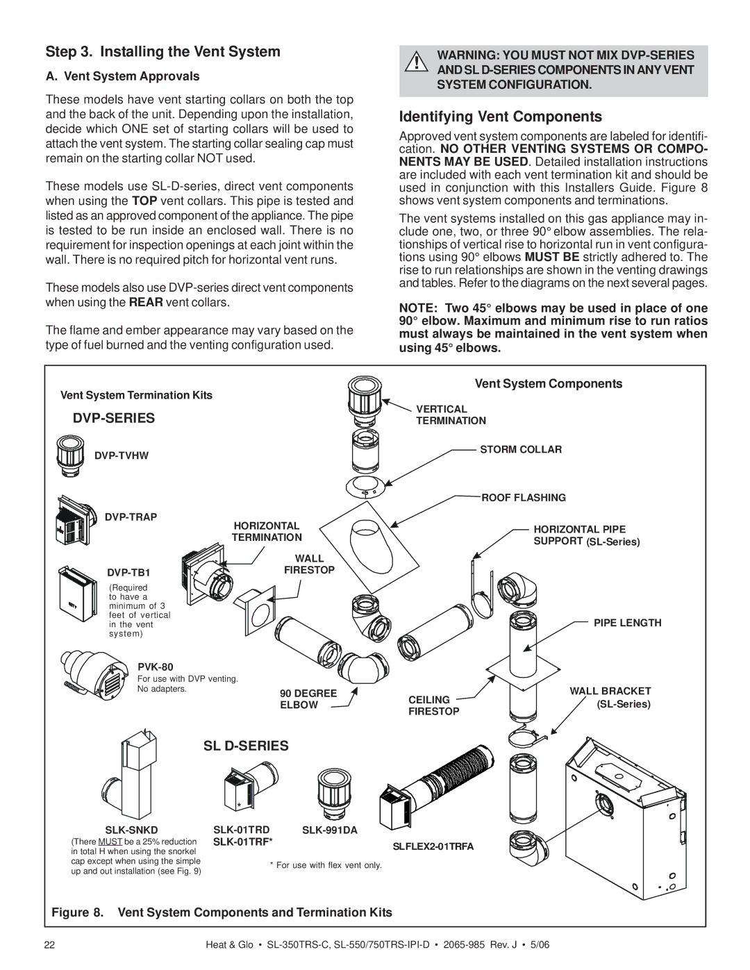
used in conjunction with this Installers Guide. Figure 8 | ||||
when using the TOP vent collars. This pipe is tested and | shows vent system components and terminations. | |||
listed as an approved component of the appliance. The pipe | The vent systems installed on this gas appliance may in- | |||
is tested to be run inside an enclosed wall. There is no | clude one, two, or three 90° elbow assemblies. The rela- | |||
requirement for inspection openings at each joint within the | tionships of vertical rise to horizontal run in vent configura- | |||
wall. There is no required pitch for horizontal vent runs. | tions using 90° elbows MUST BE strictly adhered to. The | |||
|
| rise to run relationships are shown in the venting drawings | ||
These models also use | and tables. Refer to the diagrams on the next several pages. | |||
|
| |||
when using the REAR vent collars. |
| NOTE: Two 45° elbows may be used in place of one | ||
|
| |||
The flame and ember appearance may vary based on the | 90° elbow. Maximum and minimum rise to run ratios | |||
must always be maintained in the vent system when | ||||
type of fuel burned and the venting configuration used. | using 45° elbows. | |||
Vent System Termination Kits |
|
| Vent System Components | |
| VERTICAL | |||
|
| |||
| TERMINATION | |||
|
| STORM COLLAR | ||
|
|
| ||
|
|
| ROOF FLASHING | |
HORIZONTAL |
| HORIZONTAL PIPE | ||
|
| |||
| TERMINATION |
| ||
|
| SUPPORT | ||
|
|
| ||
| WALL |
|
| |
| FIRESTOP |
|
| |
(Required to have a minimum of 3 feet of vertical in the vent system)
For use with DVP venting. No adapters.
PIPE LENGTH
90 DEGREE | CEILING | WALL BRACKET | |
ELBOW | |||
FIRESTOP | |||
|
|
SL D-SERIES
*
SLK-SNKD
(There MUST be a 25% reduction in total H when using the snorkel cap except when using the simple up and out installation (see Fig. 9)
SLK-01TRD SLK-991DA
SLK-01TRF* SLFLEX2-01TRFA
* For use with flex vent only.
Figure 8. Vent System Components and Termination Kits
22 | Heat & Glo • |