Installation
4.Wiring Connection
1.All wiring must comply with local and national electrical codes.
2.Select a power source that is capable of supplying the current as required by the air conditioner.
3.Feed the power source to the unit via a distribution switch board designed for this purpose.
4.The terminal screws inside the control box may be loose due to vibration during transport. Check the screws for loose connection.
(Running the air conditioner with loose connection can overload and damage electrical components.)
5.Always ground the air conditioner with a grounding wire and connector to meet the local and national codes.
![]() 24k/34k Btu/h (1Ø)
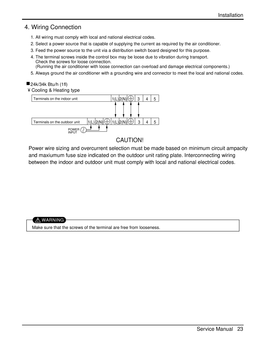
24k/34k Btu/h (1Ø)
• Cooling & Heating type
Terminals on the indoor unit | 1(L) 2(N) | 3 | 4 5 |
Terminals on the outdoor unit
1(L) 2(N) | 1(L) 2(N) | 3 | 4 | 5 |
POWER
INPUT
CAUTION!
Power wire sizing and overcurrent selection must be made based on minimum circuit ampacity and maxiumum fuse size indicated on the outdoor unit rating plate. Interconnecting wiring between the indoor and outdoor unit must comply with local and national electrical codes.
![]() WARNING
WARNING
Make sure that the screws of the terminal are free from looseness.
Service Manual 23