Installation
2) Adjusting air volume to the height of ceiling
You can choose the RPM(or air volume) of indoor motor according to the height of ceiling to supply the com- fortable atmosphere to consumers.
Procedure
1. Choose the selectable position in the table after measuring the height of ceiling.
Ceiling height | Mode of slide switch | Change of air volume | Remark | |
|
|
|
| |
more than 3.3m(10.8ft) | High Ceiling | Increasing | Maunfactured in stan- | |
|
|
| ||
2.7~3.3m(8.9~10.8ft) | Standard | - | ||
dard mode | ||||
|
|
| ||
less than 2.7m(8.9ft) | Low Ceiling | Decreasing |
| |
|
|
|
|
2. In the case of changing the height as "high" or "low", open the rear cover of the wired
3.Move the slide switch to the set position.
4.Close the rear cover and check if it works nomally.
1![]()
![]()
2![]()
![]()
3![]()
![]()
Slide switch for ceiling height
1![]()
2![]()
![]()
3![]()
1![]()
2![]()
![]()
3![]()
3) Group Control
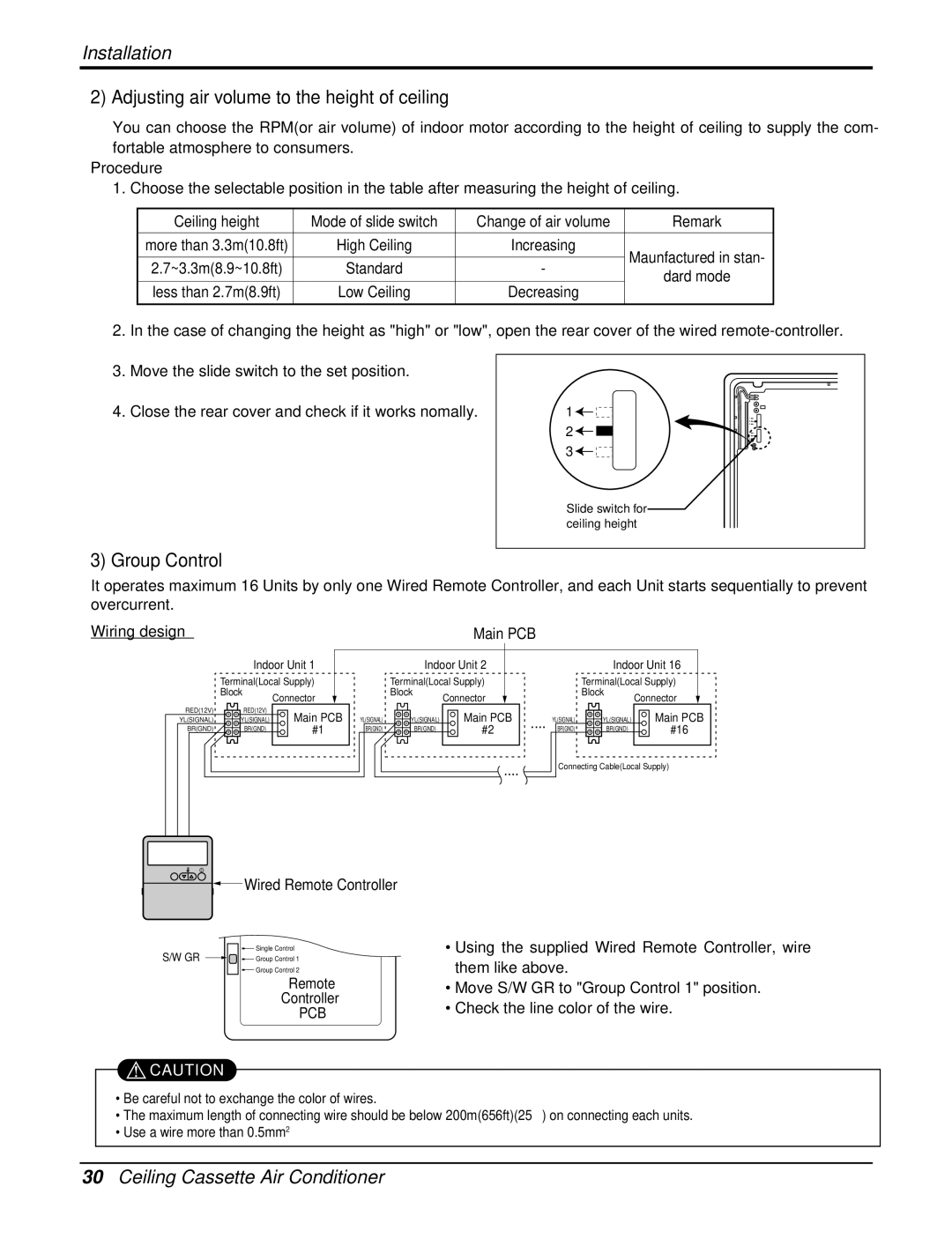
It operates maximum 16 Units by only one Wired Remote Controller, and each Unit starts sequentially to prevent overcurrent.
Wiring design | Main PCB |
Indoor Unit 1
| Terminal(Local Supply) |
| |
| Block | Connector |
|
|
|
| |
RED(12V) | RED(12V) | Main PCB |
|
YL(SIGNAL) | YL(SIGNAL) | YL(SIGNAL) | |
BR(GND) | BR(GND) | #1 | BR(GND) |
Indoor Unit 2
Terminal(Local Supply) | |
Block | Connector |
| |
YL(SIGNAL) | Main PCB |
BR(GND) | #2 |
| .... |
Indoor Unit 16
|
| Terminal(Local Supply) | |
|
| Block | Connector |
|
|
| |
.... | YL(SIGNAL) | YL(SIGNAL) | Main PCB |
BR(GND) | BR(GND) | #16 | |
|
|
| |
Connecting Cable(Local Supply)
AUTO SWING | OPERATION | SET TEMP | FAN SPEED | SUB FUNCTION | |||
|
|
| Room Temp | HI | AUTO | Heater | Preheat |
|
|
|
| MED | JET | Defrost | Humidify |
|
|
|
| LO |
| Filter | Out door |
|
|
| Time | ZONE |
| 1 2 3 4 | |
Timer | Operation unit | Program set |
|
|
|
| |
On Off |
|
|
|
|
|
|
|
Set no. Time | 01 | 03 05 07 | 09 11 13 | 15 17 | 19 | 21 | 23 |

![]() Wired Remote Controller
Wired Remote Controller
![]() Single Control
Single Control
S/W GR ![]()
![]()
![]() Group Control 1
Group Control 1
![]() Group Control 2
Group Control 2
Remote
Controller
PCB
![]() CAUTION
CAUTION
•Using the supplied Wired Remote Controller, wire them like above.
•Move S/W GR to "Group Control 1" position.
•Check the line color of the wire.
•Be careful not to exchange the color of wires.
•The maximum length of connecting wire should be below 200m(656ft)(25Ω ) on connecting each units.
•Use a wire more than 0.5mm2
30Ceiling Cassette Air Conditioner