Wiring Diagrams
Wiring Diagrams
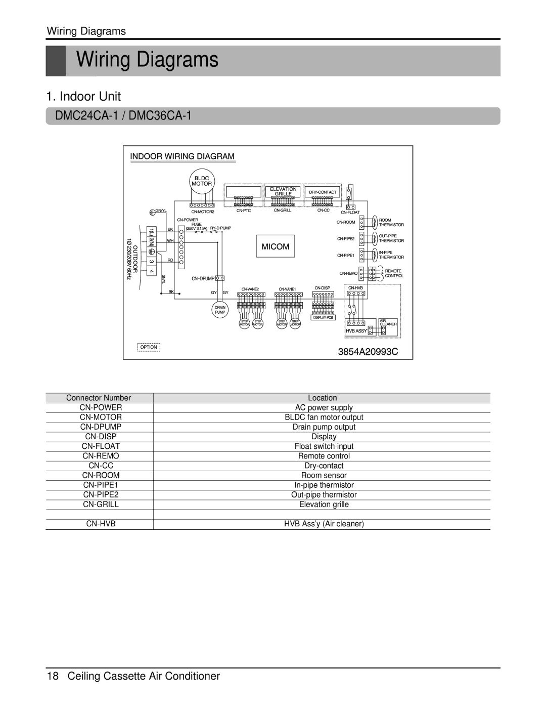
1. Indoor Unit
|
|
Connector Number | Location |
AC power supply | |
BLDC fan motor output | |
Drain pump output | |
Display | |
Float switch input | |
Remote control | |
Room sensor | |
Elevation grille | |
|
|
HVB Ass'y (Air cleaner) |
18Ceiling Cassette Air Conditioner