Only for authorized service personnel
HEAT CONTROLLER, INC
Wall Mounted Multi-SplitSystem
Air Conditioning/Heat Pump
2Multi type Air Conditioner
TABLE OF CONTENTS
SymbolsUsedinthisManual
Service Manual
Combination table
Combination table
Safety Precautions
Installation
Safety Precautions
4Multi type Air Conditioner
Service Manual
Safety Precautions
Do not install, remove, or re
6Multi type Air Conditioner
Safety Precautions
When the product is soaked
an Authorized Service Center
Installation
Safety Precautions
Install the drain hose to ensure that
installing the product
Safety Precautions
Operational
8Multi type Air Conditioner
Safety Precautions
Service Manual
•Be careful and avoid personal injury
•They may burn or explode
Dimensions
Dimensions
IndoorUnit
Split Type Indoor
OutdoorUnit
Dimensions
Service Manual
UE 18kBtu/h
Product Specifications
Product Specifications
12Multi type Air Conditioner
Outdoor Unit
Product Specifications
Service Manual
Indoor Unit
B-DMH18DB-1
Installation
InstallationParts
InstallationTools
Installation
Select the best location
Installation
Rooftop Installations
Indoor unit
Piping length and elevation
16Multi type Air Conditioner
Installation
Multi Piping Type
Service Manual
Fixing Installation Plate
Installation
Flaring Work and Connection of Piping
Flaringwork
Flaring Work and Connection of Piping
18Multi type Air Conditioner
Connecting the Piping
For right rear piping
Service Manual
Flaring Work and Connection of Piping
20Multi type Air Conditioner
Flaring Work and Connection of Piping
Flaring Work and Connection of Piping
For left rear piping
Service Manual
Flaring Work and Connection of Piping
22Multi type Air Conditioner
Indoor unit installation
Flaring Work and Connection of Piping
REMOTE CONTROL PREPARATIONOPTIONAL
HOW TO MOUNT ONTO A WALL HOW TO INSERT BATTERIES
Outdoor
24Multi type Air Conditioner
Flaring Work and Connection of Piping
Connectthe cabletotheIndoorunit
Service Manual
Flaring Work and Connection of Piping
Line voltage 208~230V
Every wire must be connected firmly
Connectthe cabletotheOutdoor unit
26Multi type Air Conditioner
Service Manual
Connectionmethod ofthe connectingcableExample
How to connect wiring to the terminals
rating on the unit rating plate
Connectthecable totheindoorunit
28Multi type Air Conditioner
Checkingthedrainage
Service Manual
To check the drainage
Drain piping
Formingthe piping
30Multi type Air Conditioner
Service Manual
Air Purging and Evacuation
Checkingmethod
Air Purging and Evacuation
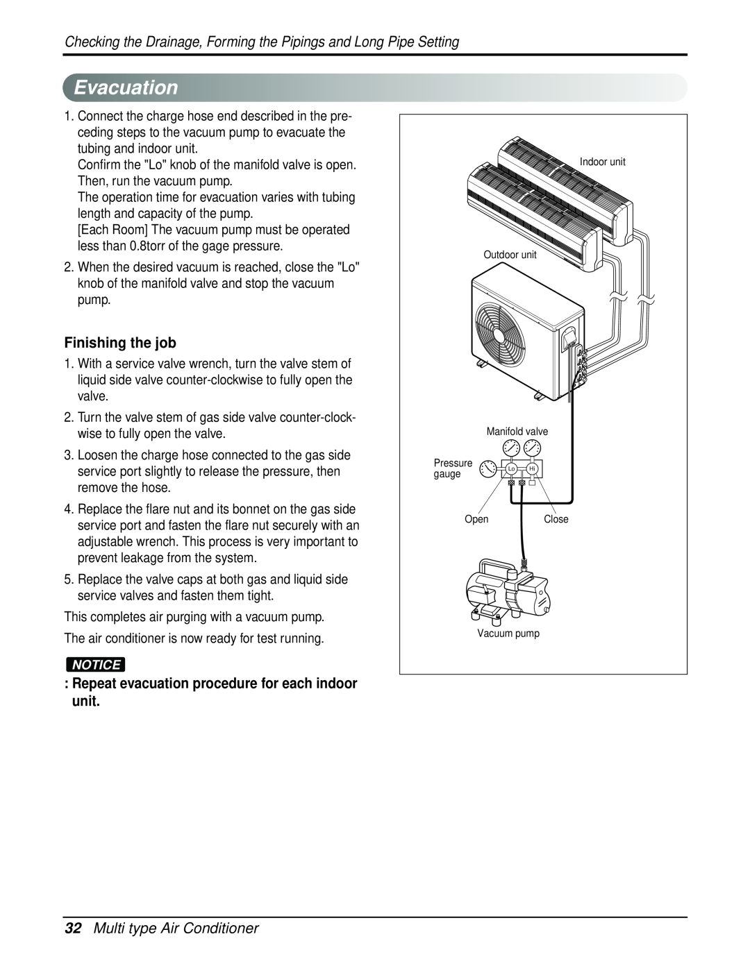
Evacuation
32Multi type Air Conditioner
Repeat evacuation procedure for each indoor unit
Finishing the job
Important:Unit is critically charge
Charging
Charging
Test Running
Test Running
34Multi type Air Conditioner
Prepare remote control
Operation
Functionofcontrol
1. MAIN UNIT FUNCTION
Operation
36Multi type Air Conditioner
Operation
Defrost ControlHeating
Fuzzy Operation
On-TimerOperation
Off-TimerOperation
Service Manual
Operation
38Multi type Air Conditioner
Off-Timer = On-TimerOperation
Sleep Timer Operation
Operation
Service Manual
Operation
Forced Operation
Buzzer Sounding Operation
FunctionofIndoorUnit
40Multi type Air Conditioner
Operation ON/OFF by Remote controller
Time Delay Safety Control
FunctionofOutdoor Unit
Service Manual
Operation
Operating Step
RemoteControlOperation
42Multi type Air Conditioner
SETTING BUTTONS
7ON/OFF TIMER BUTTONS
Disassembly
Disassembly
Indoor Unit
To remove the Grille from the Chassis
44Multi type Air Conditioner
Disassembly
2. To remove the Control Box
3.To remove the Discharge Grille
Service Manual
Disassembly
5.To remove the Motor Cover
6.To remove the Cross-FlowFan
Schematic Diagram
Schematic Diagram
ElectronicControlDevice
1.Indoor Unit
TMP87CM41F
2. Outdoor Unit
Schematic Diagram
48 Multi type Air Conditioner
Schematic Diagram
Wiring Diagram
1. Room Type Indoor Unit 2. Outdoor Unit
Schematic Diagram
Service Manual
ComponentsLocations
1. Indoor Unit
•TOP VIEW
• BOTTOM VIEW
Schematic Diagram
2. Display ASSEMBLY 1 Split Type 6871A20682A
3. Outdoor Unit
52Multi type Air Conditioner
Schematic Diagram
1 Component side
Schematic Diagram
2 Solder side
Troubleshooting Guide
RefrigerationCycleDiagram
Troubleshooting Guide
54Multi type Air Conditioner
Indoor Error
Outdoor Error
Self-diagnosisFunction
Troubleshooting Guide
CycleTroubleshooting Guide
Trouble analysis
56Multi type Air Conditioner
Troubleshooting Guide
ElectronicPartsTroubleshooting Guide
Trouble
The Product doesn’t operate at all
Troubleshooting Guide
Product doesnt operate with the remote controller
58Multi type Air Conditioner
Troubleshooting Guide
Trouble
The Compressor/Outdoor Fan are dont operate
Troubleshooting Guide
Service Manual
Trouble
Trouble 4 When indoor Fan does not operate
When indoor Fan does not operate
60Multi type Air Conditioner
Troubleshooting Guide
Trouble 5 When the louver does not operate
When Vertical Louver does not operate
Troubleshooting Guide
Service Manual
ErrorCode
62Multi type Air Conditioner
Troubleshooting Guide
Trouble Shooting
Troubleshooting Guide
Power input AC 230V.Outdoor, Indoor
• The connecting wires are misconnected
Title
64Multi type Air Conditioner
Troubleshooting Guide
Error
Cause of error
Service Manual
Troubleshooting Guide
Cause of error
Title
2-way, 3-wayValve
2-way, 3-wayValve
66Multi type Air Conditioner
2-wayValve Liguid Side
1 Pumping down
Service Manual
2-way, 3-wayValve
2.Operate the unit for 10 to 15 minutes
2 Evacuation
68Multi type Air Conditioner
7.Mount the valve caps and the service port caps
2-way, 3-wayValve
3 Gas Charging
Service Manual
2-way, 3-wayValve
After Evacuation
HEAT CONTROLLER, INC
1900 WELLWORTH AVENUE • JACKSON, MICHIGAN
THE QUALITY LEADER IN CONDITIONING AIR
05/15/07