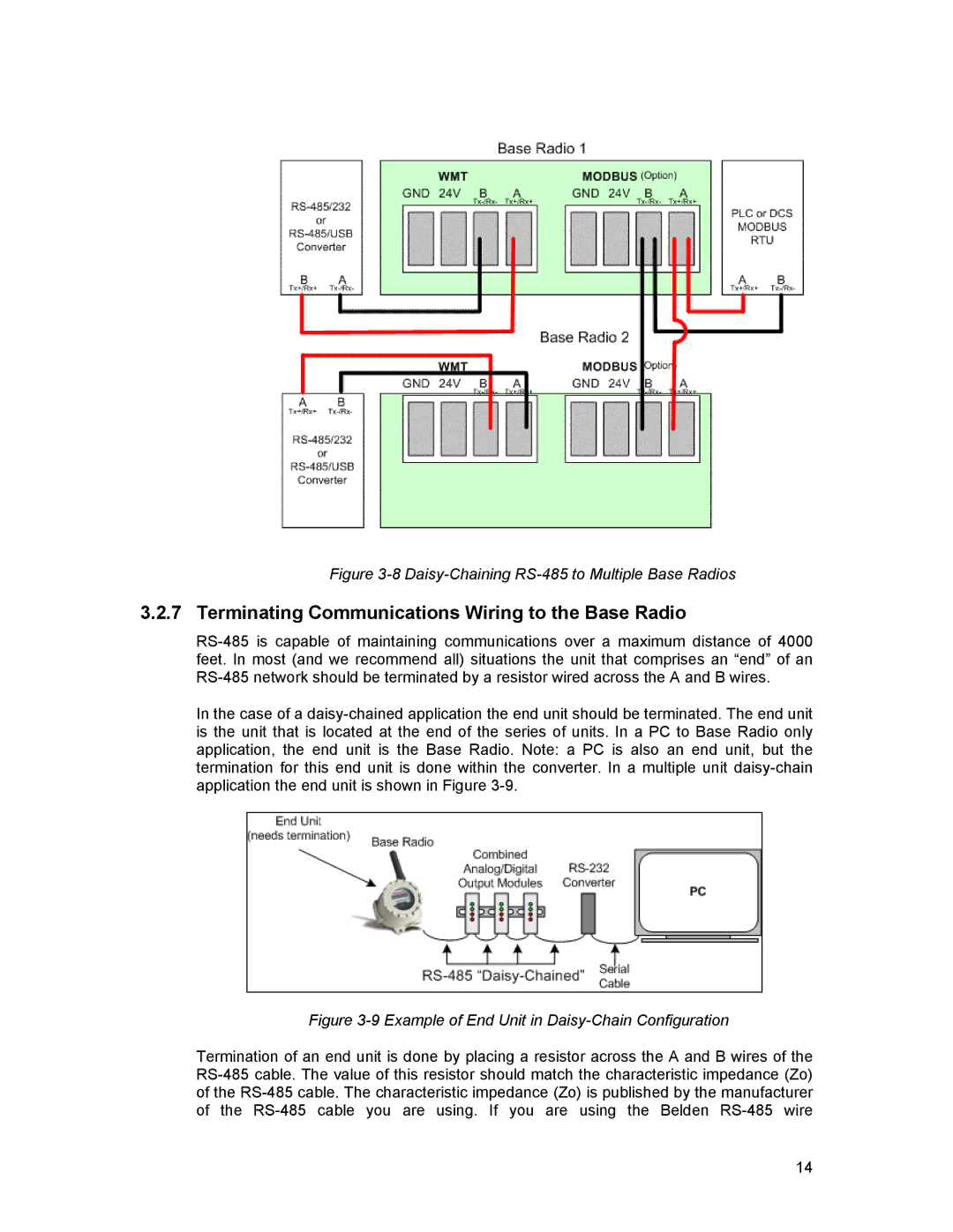
Figure 3-8 Daisy-Chaining RS-485 to Multiple Base Radios
3.2.7 Terminating Communications Wiring to the Base Radio
RS-485 is capable of maintaining communications over a maximum distance of 4000 feet. In most (and we recommend all) situations the unit that comprises an “end” of an RS-485 network should be terminated by a resistor wired across the A and B wires.
In the case of a daisy-chained application the end unit should be terminated. The end unit is the unit that is located at the end of the series of units. In a PC to Base Radio only application, the end unit is the Base Radio. Note: a PC is also an end unit, but the termination for this end unit is done within the converter. In a multiple unit daisy-chain application the end unit is shown in Figure 3-9.
Figure 3-9 Example of End Unit in Daisy-Chain Configuration
Termination of an end unit is done by placing a resistor across the A and B wires of the RS-485 cable. The value of this resistor should match the characteristic impedance (Zo) of the RS-485 cable. The characteristic impedance (Zo) is published by the manufacturer of the RS-485 cable you are using. If you are using the Belden RS-485 wire
14

