6.5.4 Transmitter Device Status Registers
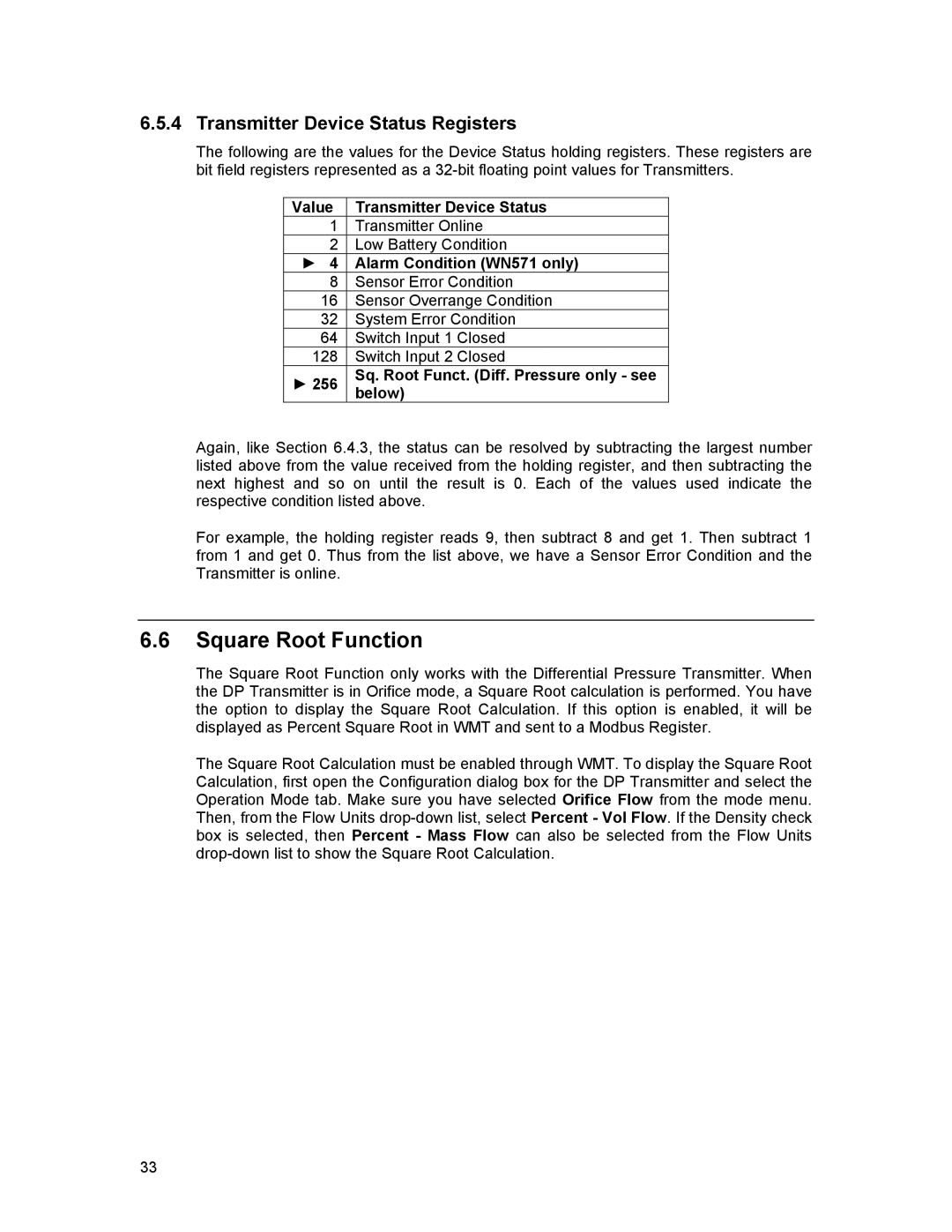
The following are the values for the Device Status holding registers. These registers are bit field registers represented as a
Value | Transmitter Device Status |
1 | Transmitter Online |
2 | Low Battery Condition |
► 4 | Alarm Condition (WN571 only) |
8 | Sensor Error Condition |
16 | Sensor Overrange Condition |
32 | System Error Condition |
64 | Switch Input 1 Closed |
128 | Switch Input 2 Closed |
► 256 | Sq. Root Funct. (Diff. Pressure only - see |
| below) |
Again, like Section 6.4.3, the status can be resolved by subtracting the largest number listed above from the value received from the holding register, and then subtracting the next highest and so on until the result is 0. Each of the values used indicate the respective condition listed above.
For example, the holding register reads 9, then subtract 8 and get 1. Then subtract 1 from 1 and get 0. Thus from the list above, we have a Sensor Error Condition and the Transmitter is online.
6.6Square Root Function
The Square Root Function only works with the Differential Pressure Transmitter. When the DP Transmitter is in Orifice mode, a Square Root calculation is performed. You have the option to display the Square Root Calculation. If this option is enabled, it will be displayed as Percent Square Root in WMT and sent to a Modbus Register.
The Square Root Calculation must be enabled through WMT. To display the Square Root Calculation, first open the Configuration dialog box for the DP Transmitter and select the Operation Mode tab. Make sure you have selected Orifice Flow from the mode menu. Then, from the Flow Units
33
