6.1.3 Modbus Parity Setting
The Modbus Parity distinguishes which type of parity is used to validate each packet of information on the
Selecting EVEN or ODD parity will automatically include one STOP bit per frame. Selecting a parity of NONE will automatically include two STOP bits as per the Modbus communications specification.
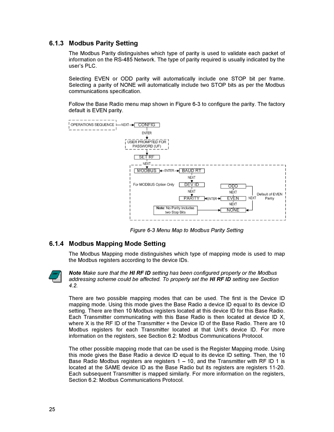
Follow the Base Radio menu map shown in Figure
Figure 6-3 Menu Map to Modbus Parity Setting
6.1.4 Modbus Mapping Mode Setting
The Modbus Mapping mode distinguishes which type of mapping mode is used to map the Modbus registers according to the device IDs.
Note Make sure that the HI RF ID setting has been configured properly or the Modbus addressing scheme could be affected. To properly set the HI RF ID setting see Section 4.2.
There are two possible mapping modes that can be used. The first is the Device ID mapping mode. Using this mode gives the Base Radio a device ID equal to its device ID setting. There are then 10 Modbus registers located at this device ID for this Base Radio. Each Transmitter communicating with this Base Radio is then located at device ID X, where X is the RF ID of the Transmitter + the Device ID of the Base Radio. There are 10 Modbus registers for each Transmitter located at that Unit’s device ID. For more information on the registers, see Section 6.2: Modbus Communications Protocol.
The other possible mapping mode that can be used is the Register Mapping mode. Using this mode gives the Base Radio a device ID equal to its device ID setting. Then, the 10 Base Radio Modbus registers are registers 1 – 10, and the Transmitter with RF ID 1 is located at the SAME device ID as the Base Radio but its registers are registers
25