•Base Radio with Modbus device ID 001
⇒Transmitter with RF ID 1 is found at Modbus device ID 002
⇒Transmitter with RF ID 2 is found at Modbus device ID 003
⇒Transmitter with RF ID 3 is found at Modbus device ID 004
•Base Radio with Modbus device ID 101
⇒Transmitter with RF ID 1 is found at Modbus device ID 102
⇒Transmitter with RF ID 2 is found at Modbus device ID 103
⇒Transmitter with RF ID 3 is found at Modbus device ID 104
More detail about the registers at each address, and their meaning, can be found in the Modbus Communications Protocol section.
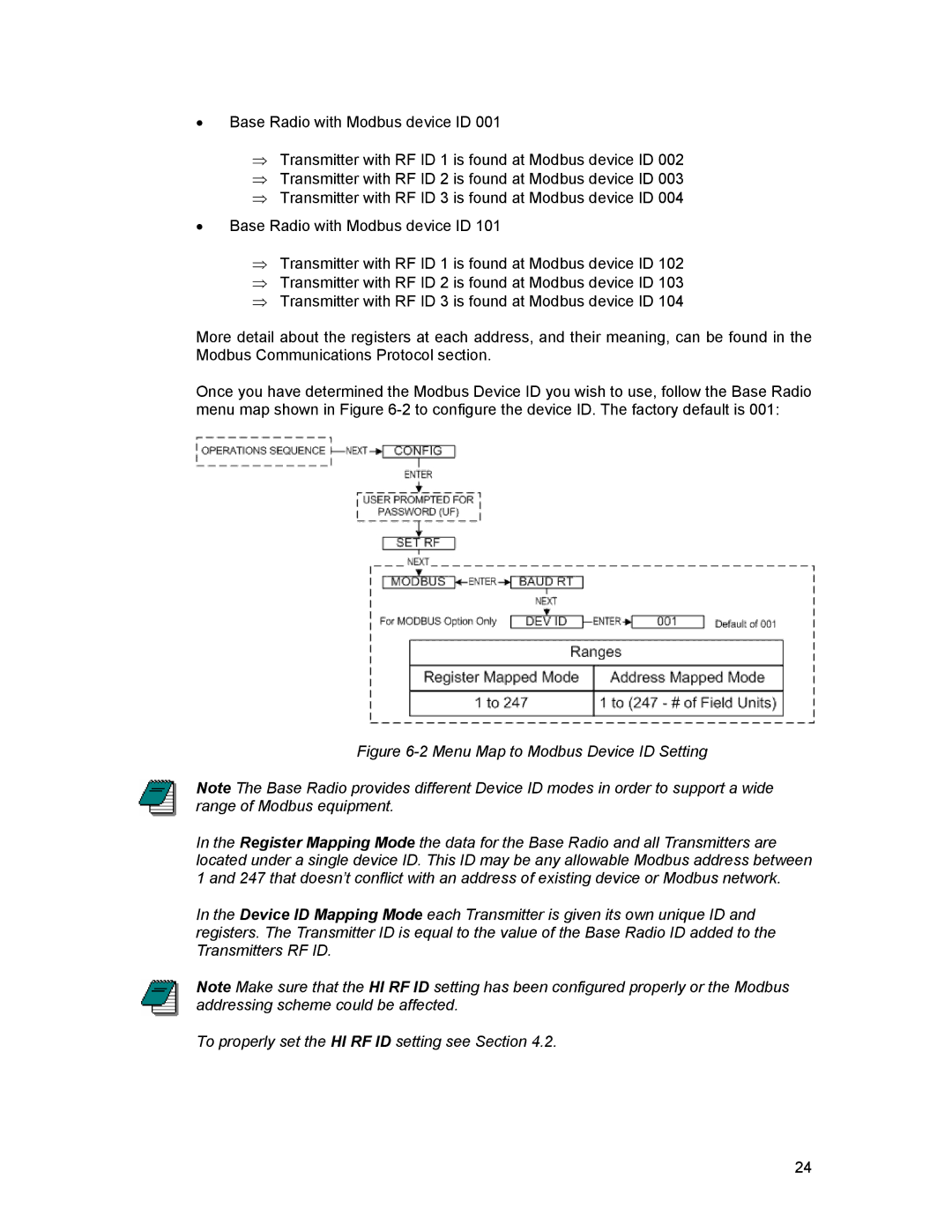
Once you have determined the Modbus Device ID you wish to use, follow the Base Radio menu map shown in Figure
Figure 6-2 Menu Map to Modbus Device ID Setting
Note The Base Radio provides different Device ID modes in order to support a wide range of Modbus equipment.
In the Register Mapping Mode the data for the Base Radio and all Transmitters are located under a single device ID. This ID may be any allowable Modbus address between 1 and 247 that doesn’t conflict with an address of existing device or Modbus network.
In the Device ID Mapping Mode each Transmitter is given its own unique ID and registers. The Transmitter ID is equal to the value of the Base Radio ID added to the Transmitters RF ID.
Note Make sure that the HI RF ID setting has been configured properly or the Modbus addressing scheme could be affected.
To properly set the HI RF ID setting see Section 4.2.
24