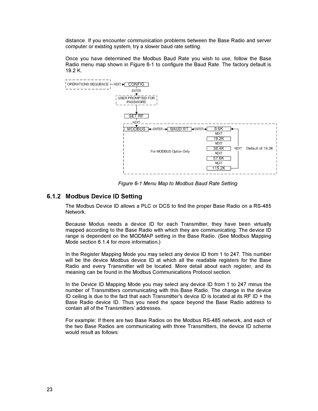
distance. If you encounter communication problems between the Base Radio and server computer or existing system, try a slower baud rate setting.
Once you have determined the Modbus Baud Rate you wish to use, follow the Base Radio menu map shown in Figure
Figure 6-1 Menu Map to Modbus Baud Rate Setting
6.1.2 Modbus Device ID Setting
The Modbus Device ID allows a PLC or DCS to find the proper Base Radio on a
Because Modus needs a device ID for each Transmitter, they have been virtually mapped according to the Base Radio with which they are communicating. The device ID range is dependent on the MODMAP setting in the Base Radio. (See Modbus Mapping Mode section 6.1.4 for more information.)
In the Register Mapping Mode you may select any device ID from 1 to 247. This number will be the device Modbus device ID at which all the readable registers for the Base Radio and every Transmitter will be located. More detail about each register, and its meaning can be found in the Modbus Communications Protocol section.
In the Device ID Mapping Mode you may select any device ID from 1 to 247 minus the number of Transmitters communicating with this Base Radio. The change in the device ID ceiling is due to the fact that each Transmitter’s device ID is located at its RF ID + the Base Radio device ID. Thus you need the space beyond the Base Radio address to contain all of the Transmitters’ addresses.
For example: If there are two Base Radios on the Modbus
23