–One LED in the center of the power supply side to indicate the overall switch status.
•Two universal input and redundant power supplies with AC switches and
•Two fan trays, each containing two fans. Air is pulled in through the rear intake and pushed out through the vents on the SFP media side. The fans provide adequate cooling for the maximum switch power rating of 102 Watts.
•Three digital thermometers, capable of sensing a temperature range from
•A motherboard that is completely enclosed in an EMI (electromagnetic interference) enclosure tray. The logic and chassis ground are connected to the chassis by screws. The embedded processor can process frames up to 1024 bytes.
•A
SFP Media Side
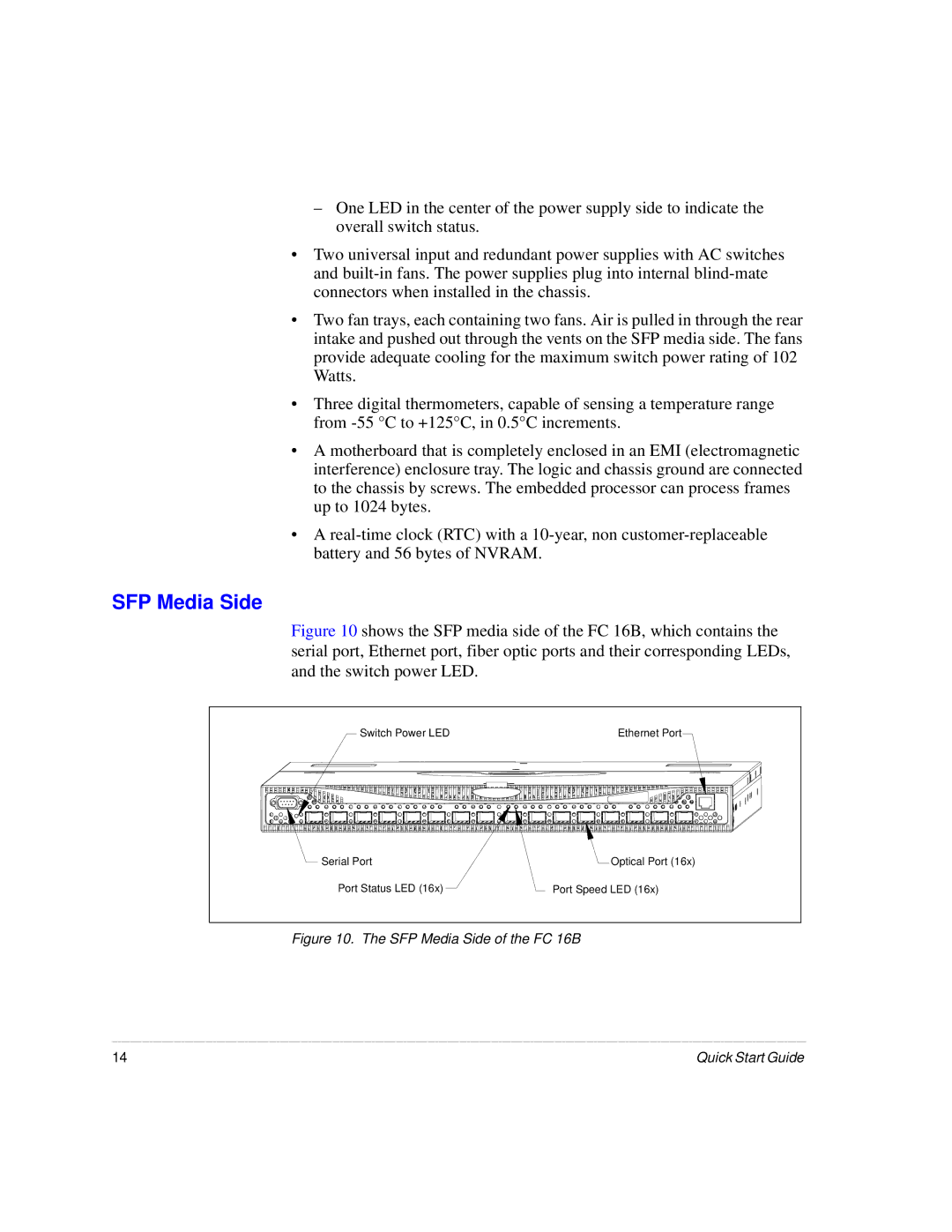
Figure 10 shows the SFP media side of the FC 16B, which contains the serial port, Ethernet port, fiber optic ports and their corresponding LEDs, and the switch power LED.
Switch Power LED | Ethernet Port |
Serial Port | Optical Port (16x) |
Port Status LED (16x) | Port Speed LED (16x) |
Figure 10. The SFP Media Side of the FC 16B
14 | Quick Start Guide |
