The following table describes the LEDs below the serial port. These LEDs indicate the switch power.
Color of LED | Status of Hardware | Recommended Action |
|
|
|
No light | Either the switch is off, or boot |
| is not complete, or boot has |
| failed. |
Verify that the switch is on and boot has had time to complete. If there is still no light, contact HP support.
Steady green | Switch is on and boot has | No action required. |
| successfully completed. |
|
Diagnostic failure on one or | |
green | more ports. |
Errors may be listed in the error log. Refer to the Fabric OS Procedures Guide for more information.
LEDs on the Power Supply Side
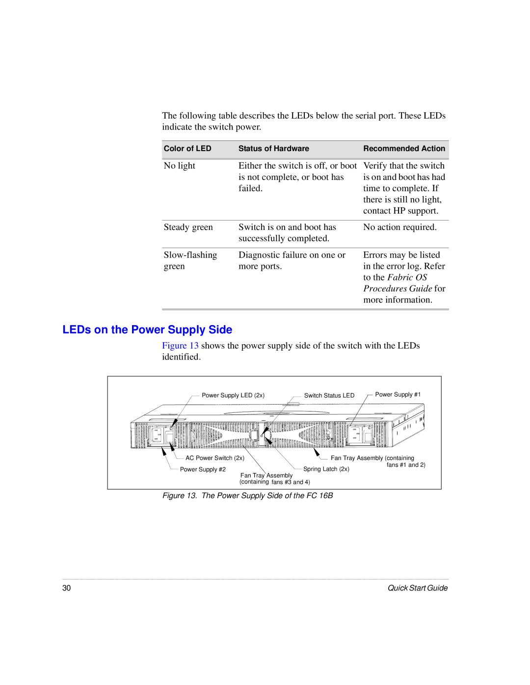
Figure 13 shows the power supply side of the switch with the LEDs identified.
Power Supply LED (2x) | Switch Status LED | Power Supply #1 |
AC Power Switch (2x) | Fan Tray Assembly (containing | |
Power Supply #2 | Spring Latch (2x) | fans #1 and 2) |
| ||
Fan Tray Assembly |
|
|
(containing fans #3 and 4) |
| |
Figure 13. The Power Supply Side of the FC 16B
30 | Quick Start Guide |
