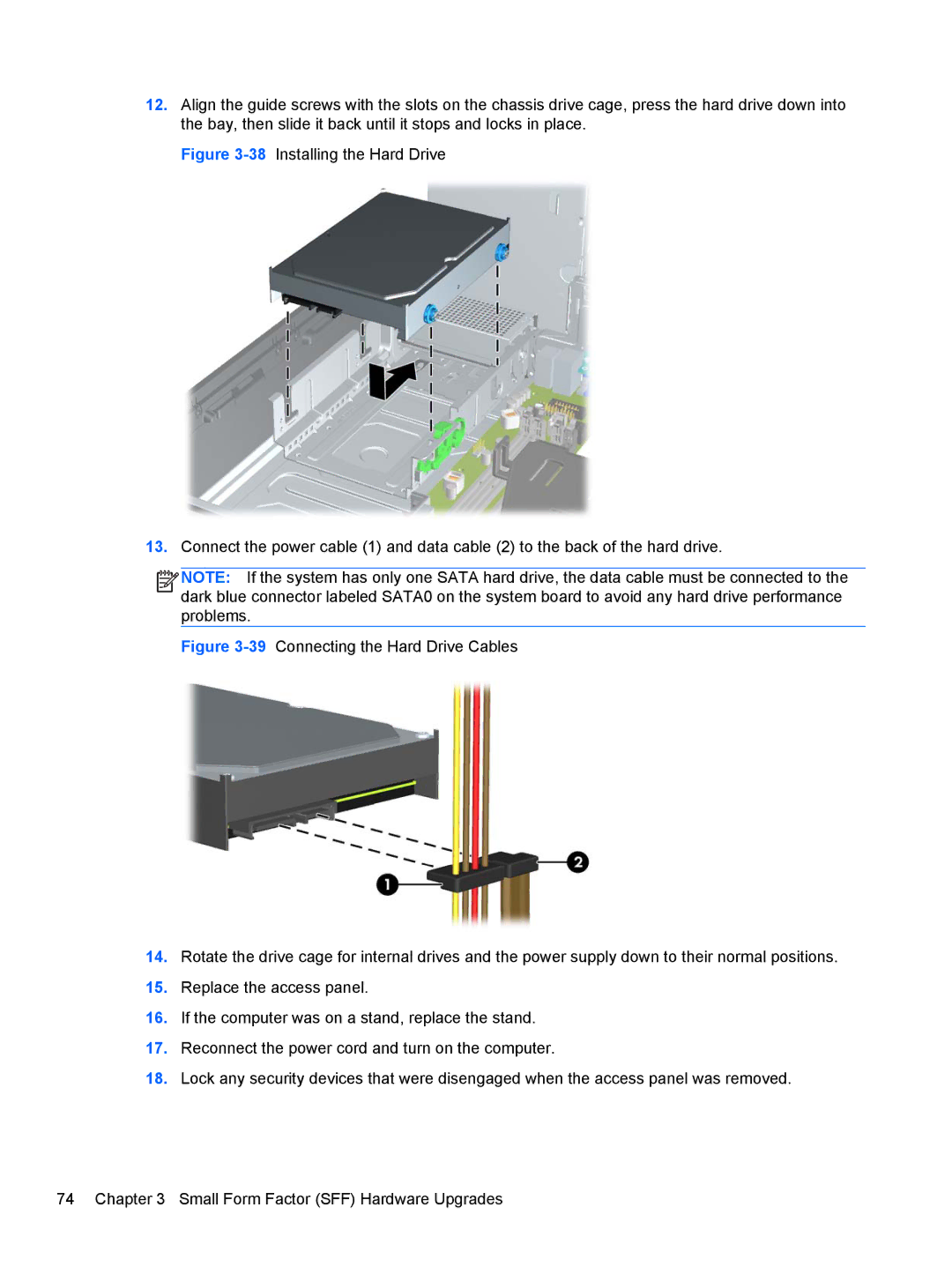
12.Align the guide screws with the slots on the chassis drive cage, press the hard drive down into the bay, then slide it back until it stops and locks in place.
Figure 3-38 Installing the Hard Drive
13.Connect the power cable (1) and data cable (2) to the back of the hard drive.
![]()
![]()
![]()
![]() NOTE: If the system has only one SATA hard drive, the data cable must be connected to the dark blue connector labeled SATA0 on the system board to avoid any hard drive performance problems.
NOTE: If the system has only one SATA hard drive, the data cable must be connected to the dark blue connector labeled SATA0 on the system board to avoid any hard drive performance problems.
