Installing the Adapter
LED Indicators
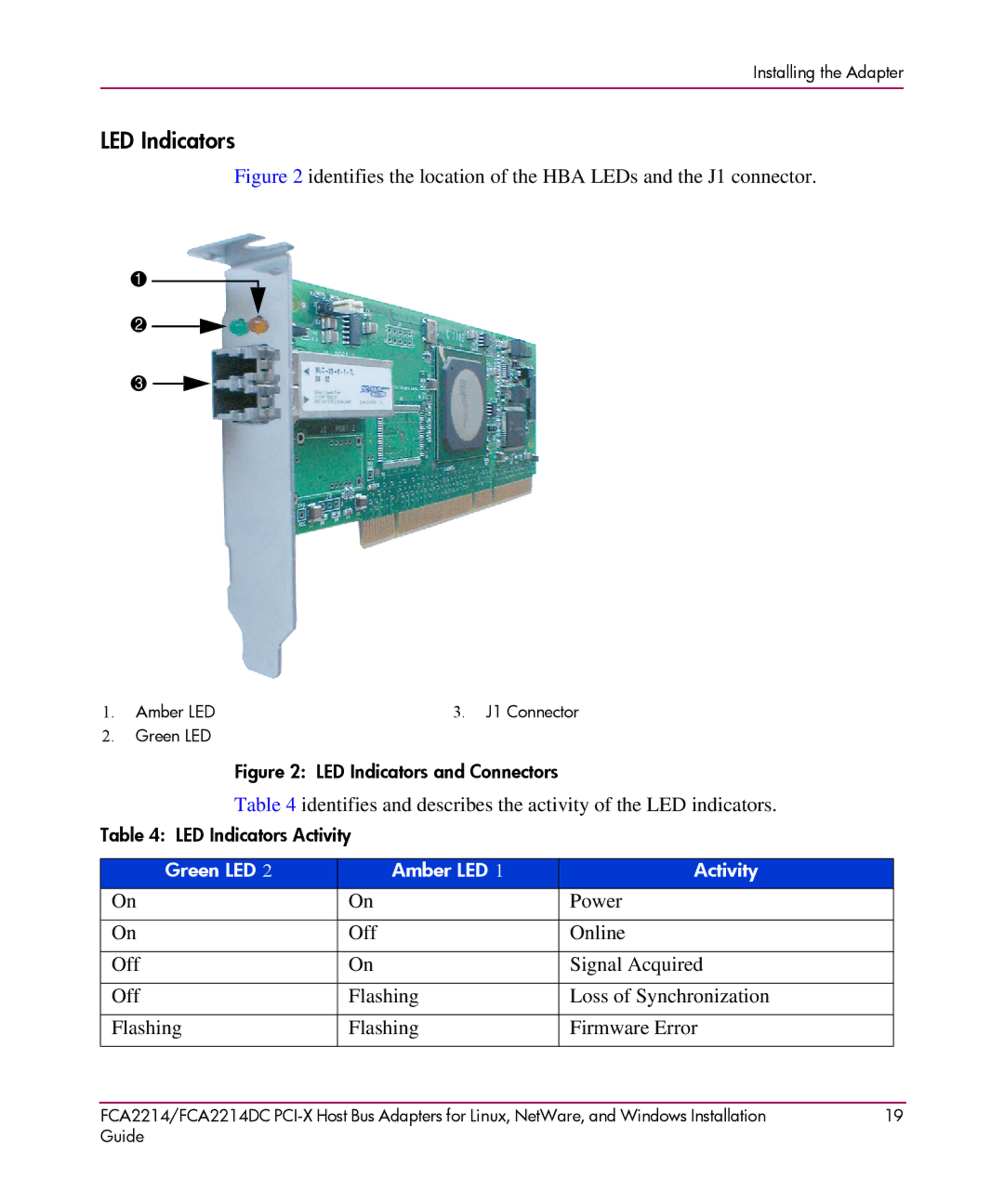
Figure 2 identifies the location of the HBA LEDs and the J1 connector.
1
2
3
1. | Amber LED | 3. J1 Connector |
2. | Green LED |
|
Figure 2: LED Indicators and Connectors
Table 4 identifies and describes the activity of the LED indicators.
Table 4: LED Indicators Activity
Green LED 2 | Amber LED 1 | Activity |
On | On | Power |
|
|
|
On | Off | Online |
|
|
|
Off | On | Signal Acquired |
|
|
|
Off | Flashing | Loss of Synchronization |
|
|
|
Flashing | Flashing | Firmware Error |
|
|
|
FCA2214/FCA2214DC | 19 |
Guide |
|