Installing HyperFabric
Installing HyperFabric Switches
Installing the HF2 Switch
This section contains information for installing an HF2 switch.
The front of the HF2 switch has a
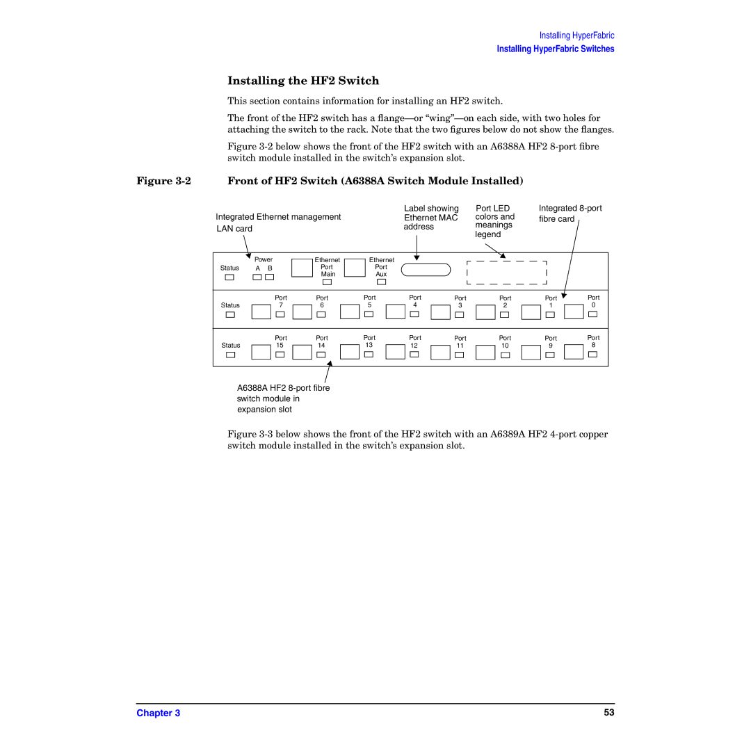
Figure 3-2 below shows the front of the HF2 switch with an A6388A HF2 8-port fibre switch module installed in the switch’s expansion slot.
Figure 3-2 Front of HF2 Switch (A6388A Switch Module Installed)
|
|
|
|
| Label showing | Port LED | Integrated | ||
Integrated Ethernet management |
| Ethernet MAC | colors and | fibre card |
| ||||
LAN card |
|
|
|
| address |
| meanings |
|
|
|
|
|
|
|
|
| legend |
|
|
| Power | Ethernet | Ethernet |
|
|
|
|
| |
Status | A | B | Port | Port |
|
|
|
|
|
|
|
| Main | Aux |
|
|
|
|
|
|
| Port | Port | Port | Port | Port | Port | Port | Port |
Status |
| 7 | 6 | 5 | 4 | 3 | 2 | 1 | 0 |
|
| Port | Port | Port | Port | Port | Port | Port | Port |
Status |
| 15 | 14 | 13 | 12 | 11 | 10 | 9 | 8 |
A6388A HF2
Figure 3-3 below shows the front of the HF2 switch with an A6389A HF2 4-port copper switch module installed in the switch’s expansion slot.
Chapter 3 | 53 |