Which Cables Go Where?
Having cleared up (we hope) the conceptual difficulty with how Linking works and with the names of the various Link communications ports, we move on to the purely pragmatic: what size cables do I use? Where?
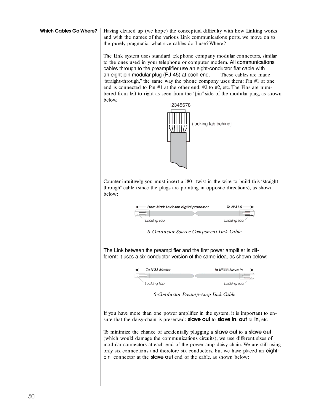
The Link system uses standard telephone company modular connectors, similar to the ones used in your telephone or computer modem. All communications cables through to the preamplifier use an
12345678
(locking tab behind)
From Mark Levinson digital processor | To Nº31.5 |
Locking tab | Locking tab |
8-Conductor Source Component Link Cable
The Link between the preamplifier and the first power amplifier is dif- ferent: it uses a
To Nº38 Master | To Nº333 Slave In |
Locking tab | Locking tab |
6-Conductor Preamp-Amp Link Cable
If you have more than one power amplifier in the system, it is important to en- sure that the
To minimize the chance of accidentally plugging a slave out to a slave out (which would damage the communications circuits), we use different sizes of modular connectors at each end of the power amp daisy chain. We are still using only six connections and therefore six conductors, but we have placed an eight- pin connector at the slave out end of the cable, as shown below:
50