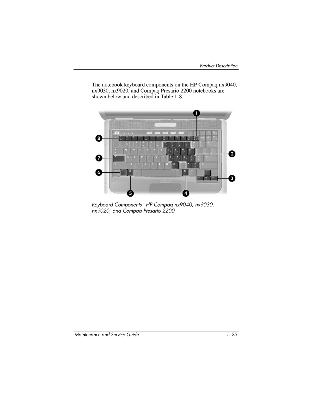
Maintenance and Service Guide
HP Pavilion ze4900 Notebook PC HP Compaq nx9040, nx9030
and nx9020 Notebook PC Compaq Presario 2200 Series Notebook
Compaq Presario 2200 Series Notebook First Edition August
Maintenance and Service Guide HP Pavilion ze4900 Notebook PC
HP Compaq nx9040, nx9030, and nx9020 Notebook PC
Document Part Number
1 Product Description
Contents
2 Troubleshooting
3 Illustrated Parts Catalog
4 Removal and Replacement Preliminaries
5 Removal and Replacement Procedures
Contents
6 Specifications A Connector Pin Assignments
B Power Cord Set Requirements
C Screw Listing Index
Product Description
Maintenance and Service Guide
Description
1.1 Models
Model Naming Conventions
Options
Description
Model Naming Conventions Continued
Maintenance and Service Guide
Options
HP Compaq nx9040, nx9030, and nx9020
Product Description
Taiwan
HP Compaq nx9040, nx9030, and nx9020 Continued
Maintenance and Service Guide
Product Description
HP Compaq nx9040, nx9030, and nx9020 Continued
Product Description
Maintenance and Service Guide
HP Compaq nx9040, nx9030, and nx9020 Continued
Product Description
HP Compaq nx9040, nx9030, and nx9020 Continued
Product Description
Maintenance and Service Guide
HP Compaq nx9040, nx9030, and nx9020 Continued
Product Description
1.2 Features
Full-size Windows keyboard with embedded numeric keypad
Support for the following optical drives
1.3 Resetting the Notebook
1.4 Power Management
Front and Right-Side Components - HP Pavilion ze4900
1.5 External Components
Maintenance and Service Guide
Product Description
Function
Front and Right-Side Components HP Pavilion ze4900
Component
Product Description
Maintenance and Service Guide
Product Description
1-17
Component
Front and Right-Side Components HP Compaq nx9040, nx9030, nx9020
and Compaq Presario
Function
Maintenance and Service Guide
Rear and Left-Side Components
HP Pavilion ze4900, HP Compaq nx9030, nx9020 and Compaq Presario
Rear and Left-Side Components - HP Pavilion ze4900
Rear and Left-Side Components
HP Pavilion ze4900, HP Compaq nx9030, nx9020
and Compaq Presario 2200 Continued
Component
Rear and Left-Side Components - HP Compaq nx9040
Rear and Left-Side Components HP Compaq nx9040
Maintenance and Service Guide
Component
Function
Rear and Left-Side Components HP Compaq nx9040 Continued
Component
Product Description
Product Description
Maintenance and Service Guide
Keyboard Components - HP Pavilion ze4900
1-23
Function
Keyboard Components HP Pavilion ze4900
Component
Product Description
Maintenance and Service Guide
Product Description
1-25
Component
Keyboard Components HP Compaq nx9040, nx9030, nx9020
and Compaq Presario
Function
Product Description
Maintenance and Service Guide
Top Components - HP Pavilion ze4900
1-27
Component
Top Components
HP Pavilion ze4900
Function
Maintenance and Service Guide
Product Description
1-29
Function
Top Components HP Compaq nx9040, nx9030, nx9020 and Compaq Presario
Component
Product Description
Product Description
Maintenance and Service Guide
Bottom Components
1-31
Function
Bottom Components
Component
Product Description
1.6 Design Overview
Troubleshooting
2.1 Computer Setup
Maintenance and Service Guide
2. Select the Main, Security, Advanced, or Tools menu
Using Computer Setup
Select Exit Load Setup Defaults, and then press enter
Select Exit Exit Saving Changes, and then press enter
Troubleshooting
Selecting from the Main Menu
Main Menu
Maintenance and Service Guide
Troubleshooting
Selecting from the Security Menu
Security Menu
Select
Advanced Menu
Selecting from the Advanced Menu
Selecting from the Tools Menu
Troubleshooting
Troubleshooting
2.2 Troubleshooting Flowcharts
Troubleshooting Flowcharts Overview
Flowchart
Is there power?
Flowchart 2.1-Initial Troubleshooting
Begin troubleshooting
Go to
“Flowchart 2.3-No Power Part 2.”
Flowchart 2.2-No Power, Part
Troubleshooting
“Flowchart 2.4-No Power Part 3.”
Maintenance and Service Guide
Flowchart 2.3-No Power, Part
Troubleshooting
“Flowchart 2.2-No Power Part 1.”
Flowchart 2.4-No Power, Part
Maintenance and Service Guide
Flowchart 2.5-No Power, Part
Troubleshooting
“Flowchart 2.4-No Power Part 3.”
Flowchart 2.6-No Video, Part
display*?
system
Maintenance and Service Guide
Flowchart 2.7-No Video, Part
Troubleshooting
2-13
go to “Flowchart 2.9-No OS Loading, Hard Drive, Part 1.”
Flowchart 2.8-No Operating System OS Loading
Troubleshooting
go to “Flowchart 2.12-No OS Loading Diskette Drive.”
“Flowchart 2.15-Nonfunctioning Device.”
Flowchart 2.9-No OS Loading, Hard Drive, Part
“Flowchart 2.12-No OS Loading Diskette Drive.”
2.10-No OS
Flowchart 2.10-No OS Loading, Hard Drive, Part
System Restore
Flowchart 2.11-No OS Loading, Hard Drive, Part
“Flowchart 2.10-No OS Loading, Hard Drive, Part 2.”
Flowchart 2.12-No OS Loading, Diskette Drive
Maintenance and Service Guide
Flowchart 2.13-No OS Loading, CD-ROM or DVD-ROM Drive
Troubleshooting
“Flowchart 2.15-Nonfunctioning Device.”
Maintenance and Service Guide
Flowchart 2.14-No Audio
Troubleshooting
2-20
Maintenance and Service Guide
Flowchart 2.15-Nonfunctioning Device
Troubleshooting
“Flowchart 2.8-No Operating System OS Loading.”
Maintenance and Service Guide
Flowchart 2.16-Nonfunctioning Keyboard
Troubleshooting
2-22
Maintenance and Service Guide
Flowchart 2.17-Nonfunctioning Pointing Device
Troubleshooting
2-23
Maintenance and Service Guide
Flowchart 2.18-No Network/Modem Connection
Troubleshooting
drivers and reconfigure
Illustrated Parts Catalog
3.1 Serial Number Location
Notebook Major Components
3.2 Notebook Major Components
Maintenance and Service Guide
Illustrated Parts Catalog
Maintenance and Service Guide
Spare Parts Notebook Major Components
Switch board
Item Description
Maintenance and Service Guide
Notebook Major Components
Illustrated Parts Catalog
Spare Part
Spare Parts Notebook Major Components Continued
Maintenance and Service Guide
Description
Maintenance and Service Guide
Notebook Major Components
Illustrated Parts Catalog
Item Description
Maintenance and Service Guide
Spare Parts Notebook Major Components Continued
Number
Maintenance and Service Guide
Notebook Major Components
Illustrated Parts Catalog
Maintenance and Service Guide
Wireless LAN antenna cables not illustrated
10 Wireless button boards includes cable
Spare Parts Notebook Major Components Continued
Illustrated Parts Catalog
Maintenance and Service Guide
Notebook Major Components
3-10
Spare Parts Notebook Major Components Continued
16 Battery packs
Maintenance and Service Guide
Spare Part
Mass Storage Devices
3.3 Mass Storage Devices
Maintenance and Service Guide
Illustrated Parts Catalog
Spare Part
Mass Storage Devices Spare Part Number Information
Maintenance and Service Guide
Description
Power cords
3.4 Miscellaneous
Spare Parts Miscellaneous not illustrated
Illustrated Parts Catalog
Removal and Replacement Preliminaries
4.1 Tools Required
4.2 Service Considerations
Cables and Connectors
Plastic Parts
4.3 Preventing Damage to Removable Drives
4.5 Packaging and Transporting Precautions
4.4 Preventing Electrostatic Damage
4.6 Workstation Precautions
4.7 Grounding Equipment and Methods
Use the following grounding precautions at workstations
Antistatic tape Antistatic smocks, aprons, and sleeve protectors
Removal and Replacement Preliminaries
Typical Electrostatic Voltage Levels
Static-Shielding Materials
Maintenance and Service Guide
Removal and Replacement Procedures
5.1 Serial Number
Removal and Replacement Procedures
5.2 Disassembly Sequence Chart
Disassembly Sequence Chart
Section
Maintenance and Service Guide
Disassembly Sequence Chart Continued
Removal and Replacement Procedures
Section
5.3 Preparing the Notebook for Disassembly
Spare Part Number Information
4. Remove the battery pack by following these steps
Spare Part Number Information
5. Remove the hard drive by following these steps
f. Remove the hard drive bezel
Removal and Replacement Procedures
Maintenance and Service Guide
Removing the Hard Drive Bezel
Removal and Replacement Procedures
h. Remove the hard drive frame i. Remove the hard drive connector
Reverse the above procedure to reassemble and install the hard drive
Maintenance and Service Guide
5.4 Notebook Feet
Removal and Replacement Procedures
Replacing the Notebook Feet
5.5 Memory Module
Reverse the above procedure to install a memory module
5.6 Mini PCI Communications Board
Spare Part Number Information
Removing a Mini PCI Communications Board
Maintenance and Service Guide
5.7 Keyboard Cover
Removal and Replacement Procedures
Spare Part Number Information
4. Turn the notebook display-side up with the front panel toward you
Spare Part Number Information
5.8 Keyboard
Removal and Replacement Procedures
5-16
Releasing the Keyboard
Maintenance and Service Guide
Reverse the above procedure to install the keyboard
Removal and Replacement Procedures
6. Remove the keyboard
5.9 Switch Board
Removing the Switch Board
7. Remove the switch board
5.10 Speakers
Removing the Speakers
5.11 Optical Drive
Spare Part Number Information
Removing the Optical Drive
Maintenance and Service Guide
5.12 Display Assembly
Removal and Replacement Procedures
Spare Part Number Information
Maintenance and Service Guide
Removing the Wireless Antenna Boards
Removal and Replacement Procedures
5-24
Maintenance and Service Guide
Removing the Display Assembly Screws
Removal and Replacement Procedures
5. Disconnect the display cable 1 from the system board
Removal and Replacement Procedures
Reverse the above procedure to install the display assembly
Removing the Display Assembly
Maintenance and Service Guide
5.13 Top Cover
Speakers Section
Spare Part Number Information
Removing the Top Cover Screws
6. Turn the notebook top-side up with the rear panel toward you
Maintenance and Service Guide
Reverse the above procedure to install the top cover
Removal and Replacement Procedures
10. Lift the top cover straight up and remove it
Maintenance and Service Guide
5.14 Heat Sink
Removal and Replacement Procedures
Spare Part Number Information
2. Disconnect the fan cable 1 from the system board
Maintenance and Service Guide
5.15 Processor
Removal and Replacement Procedures
Spare Part Number Information
Maintenance and Service Guide
Reverse the above procedure to install the processor
Removal and Replacement Procedures
3. Lift the processor 2 straight up and remove it
5.16 Wireless Button Board
Spare Part Number Information
Speakers Section
Reverse the above procedure to install the wireless button board
2. Disconnect the wireless button board cable 1 from the system board
4. Remove the wireless button board
Removing the Wireless Button Board
5.17 Diskette Drive
Spare Part Number Information
Speakers Section
Maintenance and Service Guide
Reverse the above procedure to install the diskette drive
Removal and Replacement Procedures
4. Remove the diskette drive
5.18 Diskette Drive Cover
Spare Part Number Information
Speakers Section
Maintenance and Service Guide
Reverse the above procedure to install the diskette drive cover
Removal and Replacement Procedures
3. Remove the diskette drive cover
5.19 System Board
Spare Part Number Information
Speakers Section
Removing the System Board Screws
Step 6 applies only to HP Pavilion ze4900, HP Compaq nx9030 and nx9020, and Compaq Presario 2200 notebook models
Step 7 applies only to HP Compaq nx9040 models
Removal and Replacement Procedures
Maintenance and Service Guide
5-44
10. Slide the system board away from the base enclosure at an angle
Dimensions
Specifications
Notebook
Stand-alone power requirements
Temperature
Specifications
Notebook Continued
Relative humidity noncondensing
Dimensions
15.0-inch, XGA, TFT Display
Specifications
Pixel resolution
Dimensions
14.1-inch, XGA, TFT Display
Specifications
Pixel resolution
Dimensions
4200-rpm Hard Drives
Specifications
Maintenance and Service Guide
Dimensions
Primary 6-cell, Li-Ion Battery Pack
Specifications
Energy
Dimensions
Optional 8-cell, Li-Ion Battery Pack
Specifications
Maintenance and Service Guide
Access time
24X Max DVD+RW/R and CD-RW Drive
Specifications
Applicable disk
Access time
24X Max DVD/CD-RW Combo Drive
Specifications
Maintenance and Service Guide
Data transfer rate
24X Max DVD/CD-RW Combo Drive Continued
Specifications
Startup time
Access time
8X MAX DVD-ROM Drive
Specifications
Maintenance and Service Guide
Specifications
8X MAX DVD-ROM Drive Continued
System DMA
Data transfer rate
Maintenance and Service Guide
System Interrupts
Specifications
Hardware IRQ
Hardware IRQ
System Interrupts Continued
Specifications
System Function
Maintenance and Service Guide
System I/O Addresses
Specifications
I/O Address hex
I/O Address hex
System I/O Addresses Continued
Specifications
6-16
System I/O Addresses Continued
Specifications
Maintenance and Service Guide
I/O Address hex
Size
System Memory Map
Specifications
Memory Address
Signal
Connector Pin Assignments
Table A-1 Universal Serial Bus
Signal
Connector Pin Assignments
Table A-2 RJ-45 Network
Table A-3 S-Video
Signal
Signal
Table A-4 External Monitor
Connector Pin Assignments
Signal
Connector Pin Assignments
Table A-5 RJ-11 Modem
Table A-6 Audio-In Microphone
Signal
Signal
Table A-7 Audio-Out Headphone
Connector Pin Assignments
Signal
Signal
Table A-8 Parallel
Connector Pin Assignments
Signal
Signal
Table A-9 Serial
Connector Pin Assignments
Signal
Power Cord Set Requirements
3-Conductor Power Cord Set
General Requirements
Power Cord Set Requirements
3-Conductor Power Cord Set Requirements
Country-Specific Requirements
Country
Maintenance and Service Guide
3-Conductor Power Cord Set Requirements Continued
Power Cord Set Requirements
Country
Screw Listing
Maintenance and Service Guide
Phillips M2.0×6.0 Screw Locations
Table C-1 Phillips PM2.0×6.0 Screw
Where used
Screw Listing
Maintenance and Service Guide
Table C-1 Phillips PM2.0×6.0 Screw Continued
Where used
Phillips M2.0×6.0 Screw Locations
Where used
Table C-1 Phillips PM2.0×6.0 Screw Continued
Screw Listing
Table C-1 Phillips PM2.0×6.0 Screw Continued
Where used
Maintenance and Service Guide
Phillips M2.0×6.0 Screw Locations
Where used
Table C-2 Phillips PM1.5×5.0 Shoulder Screw and PM2.5×4.0 Screw
Where used
Phillips M1.5×5.0 Shoulder Screw and PM2.5×4.0 Screw Locations
Maintenance and Service Guide
Table C-3 Phillips PM2.0×4.0 Screw
Where used
Phillips M2.0×4.0 Screw Locations
Table C-3 Phillips PM2.0×4.0 Screw Continued
Where used
Screw Listing
Table C-3 Phillips PM2.0×4.0 Screw Continued
Where used
Maintenance and Service Guide
Phillips M2.0×4.0 Screw Locations
Where used
Table C-3 Phillips PM2.0×4.0 Screw Continued
Screw Listing
Maintenance and Service Guide
Table C-4 Phillips PM2.0×3.0 Screw
Where used
Phillips M2.0×3.0 Screw Locations
Table C-4 Phillips PM2.0×3.0 Screw Continued
Where used
Screw Listing
Maintenance and Service Guide
Table C-5 Phillips PM2.0×8.0 Screw
Where used
Phillips M2.0×8.0 Screw Locations
Table C-5 Phillips PM2.0×8.0 Screw Continued
Where used
Screw Listing
Maintenance and Service Guide
Table C-6 Phillips PM2.0×5.0 Screw
Where used
Phillips M2.0×5.0 Screw Locations
Phillips M1.5×5.0 Screw Locations
Table C-7 Phillips PM1.5×5.0 Screw
Where used
Screw Listing
Maintenance and Service Guide
Table C-8 Phillips PM2.0×9.0 Screw
Where used
Phillips M2.0×9.0 Screw Locations
HM5.0×9.0 Screwlock Locations - HP Compaq nx9040 Notebook Models
Table C-9 HM5.0×9.0 Screwlock
Where used
Screw Listing
Maintenance and Service Guide
Table C-9 HM5.0×9.0 Screwlock Continued
Where used
Screw Listing
Phillips M1.5×12.0 Screw Locations
Table C-10 Phillips PM1.5×12.0 Screw
Where used
Screw Listing
Index
Page
Page
Page