Maintenance and Service Guide
Page
Contents
Removal and Replacement Preliminaries
Screw Listing Index
Product Description
Key
Models
Model Naming Conventions
FE NIC
PK349PA AB0
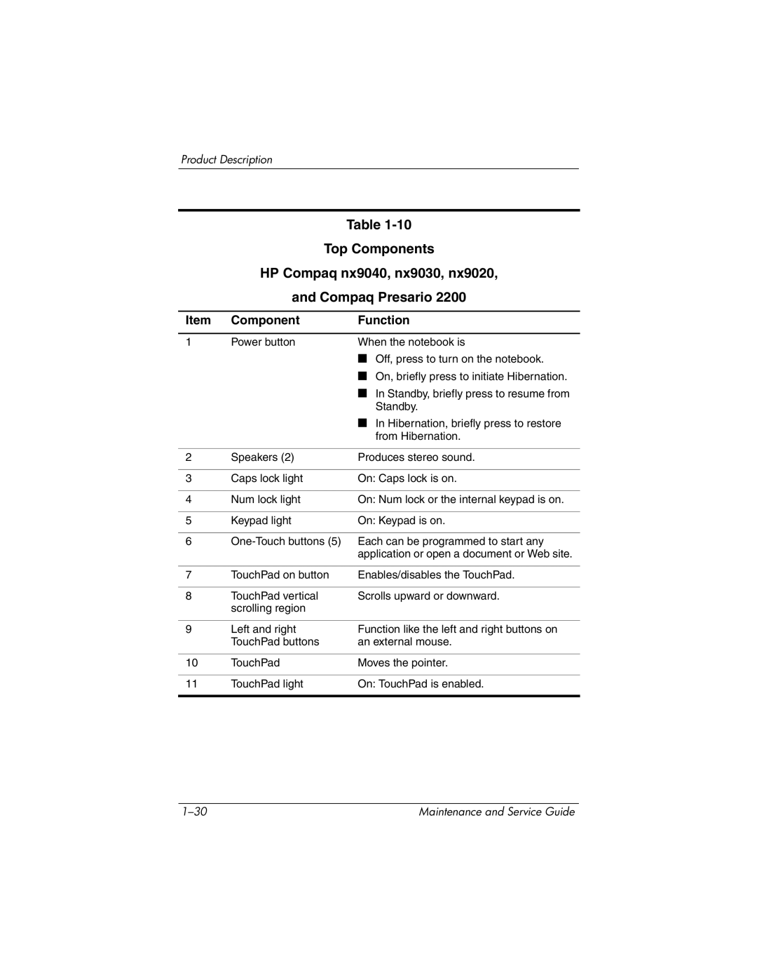
HP Compaq nx9040, nx9030, and nx9020
PK164PA AB2
PK153PA UUF
PG575ET ABF
PG569EA AKB
PG568ET UUG
Features
Product Description
Product Description
Resetting the Notebook
Power Management
External Components
Component Function
Front and Right-Side Components HP Pavilion ze4900
Product Description
HP Compaq nx9040
Component Function
Component Function
Rear and Left-Side Components HP Compaq nx9040
Rear and Left-Side Components HP Compaq nx9040
Keyboard Components HP Pavilion ze4900
Num lock key
Keyboard Components HP Pavilion ze4900
Product Description
Enables caps lock and turns on
Top Components HP Pavilion ze4900
Top Components
Product Description
Component Function
Bottom Components
Bottom Components
Design Overview
Computer Setup
Troubleshooting
Using Computer Setup
Select To Do This
Main Menu
Security Menu
Selecting from the Security Menu
Advanced Menu
Selecting from the Advanced Menu
Troubleshooting Flowcharts Overview
Troubleshooting Flowcharts
Flowchart No Power Part
Flowchart 2.1-Initial Troubleshooting
Flowchart 2.2-No Power, Part
Flowchart 2.3-No Power, Part
External
Flowchart 2.4-No Power, Part
Flowchart 2.5-No Power, Part
Press display Switch to ensure Operation Video OK? Done
Flowchart 2.6-No Video, Part
Monitor
Flowchart 2.7-No Video, Part
Go to Flowchart 2.12-No OS Loading Diskette Drive
Flowchart 2.8-No Operating System OS Loading
Loading, Hard
Flowchart 2.9-No OS Loading, Hard Drive, Part
Flowchart No OS Loading, Hard Drive, Part
Flowchart 2.10-No OS Loading, Hard Drive, Part
Can bad sectors be fixed?
Flowchart 2.11-No OS Loading, Hard Drive, Part
Utility?
Flowchart 2.12-No OS Loading, Diskette Drive
Flowchart 2.13-No OS Loading, CD-ROM or DVD-ROM Drive
Flowchart 2.14-No Audio
Cmos
Flowchart 2.15-Nonfunctioning Device
Flowchart 2.16-Nonfunctioning Keyboard
Pointing device Not operating Properly Connect notebook
Flowchart 2.17-Nonfunctioning Pointing Device
Flowchart 2.18-No Network/Modem Connection
Serial Number Location
Illustrated Parts Catalog
Illustrated Parts Catalog
Display assemblies
Switch board
Spare Parts Notebook Major Components
Spare Part
Illustrated Parts Catalog
Speakers Heat sink
Keyboards
Illustrated Parts Catalog
Diskette drive cover
Processors
System boards
Hard drive guide not illustrated
Illustrated Parts Catalog
Rubber notebook feet and screw plugs
Wireless LAN antenna cables not illustrated
Wireless button boards includes cable
Base enclosures
Illustrated Parts Catalog
Mini PCI communications boards
Mini PCI compartment cover Battery packs
Hard drives, 4200-rpm
Hard drive tray
Mass Storage Devices
Diskette drive
Mass Storage Devices Spare Part Number Information
Description Number Logo Kit
Power cords
Miscellaneous
Spare Parts Miscellaneous not illustrated
Tools Required
Removal and Replacement Preliminaries
Plastic Parts
Service Considerations
Preventing Damage to Removable Drives
Preventing Electrostatic Damage
Packaging and Transporting Precautions
Grounding Equipment and Methods
Workstation Precautions
Removal and Replacement Preliminaries
Material Use Voltage Protection Level
Typical Electrostatic Voltage Levels
Static-Shielding Materials
Relative Humidity Event 10% 40% 55%
Serial Number
Removal and Replacement Procedures
Disassembly Sequence Chart
Disassembly Sequence Chart
Section Description # of Screws Removed
Preparing the Notebook for Disassembly
Reverse the above procedure to install the battery pack
Removing the Hard Drive
Removing the Hard Drive Bezel
Disassembling the hard drive
Replacing the Notebook Feet
Memory Module
Reverse the above procedure to install a memory module
Mini PCI Communications Board
Removing a Mini PCI Communications Board
Keyboard Cover
Reverse the above procedure to install an keyboard cover
Keyboard
Releasing the Keyboard
Reverse the above procedure to install the keyboard
Switch Board
Reverse the above procedure to install the switch board
Speakers
Optical Drive
Display Assembly
Removing the Wireless Antenna Boards
Removing the Display Assembly Screws
Reverse the above procedure to install the display assembly
Speakers Section
Top Cover
Removing the Top Cover Screws
Removing the Top Cover Screws
Reverse the above procedure to install the top cover
Heat Sink
Removing the Heat Sink
Processor
Reverse the above procedure to install the processor
Wireless Button Board
Removing the Wireless Button Board
Diskette Drive
Reverse the above procedure to install the diskette drive
Diskette Drive Cover
Removing the Diskette Drive Cover
System Board
Removing the System Board Screws
Removal and Replacement Procedures
Removal and Replacement Procedures
Reverse the above procedure to install the system board
Stand-alone power requirements
Dimensions
Shock
Temperature
Relative humidity noncondensing
Maximum altitude unpressurized
Inch, XGA, TFT Display
Height 28.5 cm 11.2 Width 21.3 cm Diagonal 35.8 cm 14.1
Rpm Hard Drives
Energy
Primary 6-cell, Li-Ion Battery Pack
Optional 8-cell, Li-Ion Battery Pack
24X Max DVD+RW/R and CD-RW Drive
24X Max DVD/CD-RW Combo Drive
24X Max DVD/CD-RW Combo Drive
8X MAX DVD-ROM Drive
Hardware DMA System Function
System DMA
Hardware IRQ System Function
System Interrupts
IRQ12
Address hex
System I/O Addresses
16F Unused
VGA
Size Memory Address System Function
System Memory Map
Table A-1 Universal Serial Bus
Pin Signal
Table A-3 Video
Table A-2 RJ-45 Network
Table A-4 External Monitor
Table A-6 Audio-In Microphone
Pin Signal Audio-in Ground
Table A-5 RJ-11 Modem
Table A-7 Audio-Out Headphone
Pin Signal Audio-out Ground
Table A-8 Parallel
Table A-9 Serial
General Requirements
Conductor Power Cord Set
Country Accredited Agency Applicable Note Number
Conductor Power Cord Set Requirements
Country-Specific Requirements
BSI
Screw Listing
Head
Color Qty Length Thread Width Black Where used
Table C-1 Phillips PM2.0×6.0 Screw
Table C-1 Phillips PM2.0×6.0 Screw
Table C-1 Phillips PM2.0×6.0 Screw
Table C-1 Phillips PM2.0×6.0 Screw
Table C-2 Phillips PM1.5×5.0 Shoulder Screw PM2.5×4.0 Screw
Color Qty Length Thread Width Silver Head Where used
Table C-3 Phillips PM2.0×4.0 Screw
Table C-3 Phillips PM2.0×4.0 Screw
Table C-3 Phillips PM2.0×4.0 Screw
Table C-3 Phillips PM2.0×4.0 Screw
Table C-4 Phillips PM2.0×3.0 Screw
Color Qty Length Thread Width Silver Where used
Table C-4 Phillips PM2.0×3.0 Screw
Table C-5 Phillips PM2.0×8.0 Screw
Table C-5 Phillips PM2.0×8.0 Screw
Table C-6 Phillips PM2.0×5.0 Screw
Table C-7 Phillips PM1.5×5.0 Screw
Table C-8 Phillips PM2.0×9.0 Screw
Table C-9 HM5.0×9.0 Screwlock
Head Color Qty. Length Thread Width
Table C-10 Phillips PM1.5×12.0 Screw
Color Qty Length Thread Width Silver 12.0 mm Where used
Index
Index
Index-3
Index-4
Index-5
Index-6