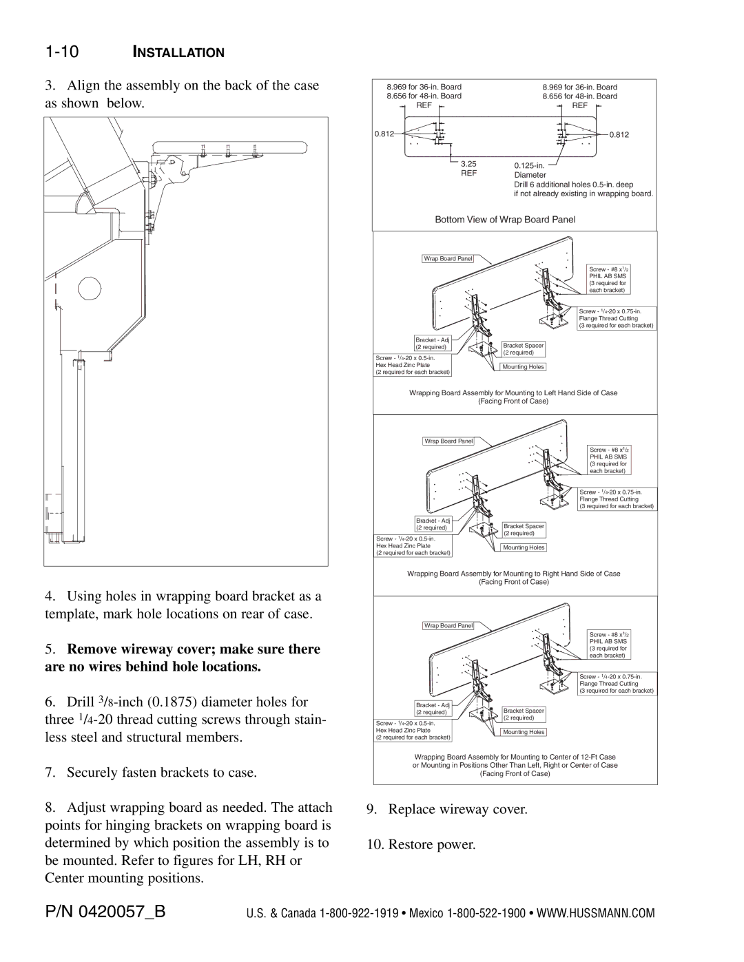
P/N 0420057_B specifications
The Hussman P/N 0420057_B represents a cutting-edge refrigeration solution designed for modern retail environments, particularly those requiring efficient display systems for perishable goods. As part of Hussman's extensive product lineup, this unit integrates advanced technologies tailored to enhance both performance and energy efficiency.One of the standout features of the 0420057_B is its state-of-the-art refrigeration system, which employs a combination of environmentally friendly refrigerants and high-efficiency compressors. This design not only supports compliance with stringent environmental regulations but also contributes to reduced energy consumption, ultimately leading to lower operational costs for retailers. The unit is built to maintain consistent temperatures, ensuring that products are stored and displayed at optimal conditions, thus prolonging freshness and quality.
Another key characteristic of the Hussman P/N 0420057_B is its user-friendly interface. Retail staff can easily monitor and adjust temperature settings, ensuring that the display conditions meet specific product requirements. This feature enhances operational efficiency and minimizes the risk of temperature-related spoilage. Additionally, digital temperature controls come equipped with alarms that alert staff to any fluctuations, acting as a safeguard for perishable inventory.
The design of the unit emphasizes practicality and aesthetics. With a sleek, modern appearance, the 0420057_B fits seamlessly into various store layouts while maximizing product visibility. The glass door design allows for enhanced product presentation, attracting customers and facilitating easy access for quick purchasing decisions.
Durability is a crucial characteristic of Hussman products, and the 0420057_B is no exception. Constructed from high-quality materials, this refrigeration unit is designed to withstand the rigors of daily retail operations. The robust build ensures longevity, reducing maintenance frequency and operational downtimes, which are critical aspects for retailers aiming to enhance their profit margins.
Moreover, the Hussman P/N 0420057_B incorporates intelligent technology, such as smart sensors that optimize energy use based on real-time conditions. This capability not only enhances energy efficiency but also supports retailers in meeting sustainability goals, making this unit a valuable addition to any eco-conscious business strategy.
In conclusion, the Hussman P/N 0420057_B is a versatile refrigeration solution that combines advanced technology, user-friendly features, and sleek design to meet the demanding needs of modern retail environments. Its focus on energy efficiency, durability, and optimal product preservation makes it an essential investment for retailers looking to enhance their operational effectiveness while ensuring customer satisfaction.

