Management module
Active LED
IP reset button
Management module error LED
OK | Ethernet link |
| LED |
LINK
![]()
![]() TX/RX
TX/RX
Ethernet activity
LED
IP
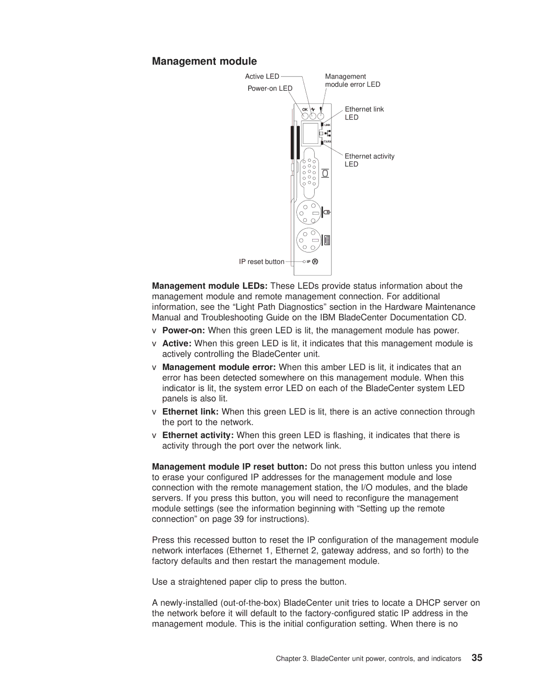
Management module LEDs: These LEDs provide status information about the management module and remote management connection. For additional information, see the “Light Path Diagnostics” section in theHardware Maintenance Manual and Troubleshooting Guide on the IBM BladeCenter Documentation CD.
v
vActive: When this green LED is lit, it indicates that this management module is actively controlling the BladeCenter unit.
vManagement module error: When this amber LED is lit, it indicates that an error has been detected somewhere on this management module. When this indicator is lit, the system error LED on each of the BladeCenter system LED panels is also lit.
vEthernet link: When this green LED is lit, there is an active connection through the port to the network.
vEthernet activity: When this green LED is flashing, it indicates that there is activity through the port over the network link.
Management module IP reset button: Do not press this button unless you intend to erase your configured IP addresses for the management module and lose connection with the remote management station, the I/O modules, and the blade servers. If you press this button, you will need to reconfigure the management module settings (see the information beginning with “Setting up the remote connection” on page 39 for instructions).
Press this recessed button to reset the IP configuration of the management module network interfaces (Ethernet 1, Ethernet 2, gateway address, and so forth) to the factory defaults and then restart the management module.
Use a straightened paper clip to press the button.
A
Chapter 3. BladeCenter unit power, controls, and indicators 35
