Multiport aggregation group 1 Gbps or 100 Mbps links
|
|
|
|
|
|
|
|
| Switch A |
1 | 2 | 3 | 4 | 5 | 6 | 7 | 8 | 9 | 10 11 12 13 14 |
|
|
|
|
|
|
|
|
| Mgmt |
|
|
|
|
|
|
|
|
| Mod |
|
|
|
|
|
|
|
|
| Switch B |
|
|
|
|
|
|
|
|
| Switch A |
1 | 2 | 3 | 4 | 5 | 6 | 7 | 8 | 9 | 10 11 12 13 14 |
|
|
|
|
|
|
|
|
| Mgmt |
|
|
|
|
|
|
|
|
| Mod |
|
|
|
|
|
|
|
|
| Switch B |
|
|
|
|
|
|
|
|
| Switch A |
1 | 2 | 3 | 4 | 5 | 6 | 7 | 8 | 9 | 10 11 12 13 14 |
|
|
|
|
|
|
|
|
| Mgmt |
|
|
|
|
|
|
|
|
| Mod |
|
|
|
|
|
|
|
|
| Switch B |
L2 Switch
![]() 10/100 Mbps management links
10/100 Mbps management links
L2+ Switch
Dual external switches
L2+ Switch
IBM Director
-Chassis management
-Application deployment
-Internal switches
Establishment backbone
Network administrator
-Infrastructure management
-Network hardware and software
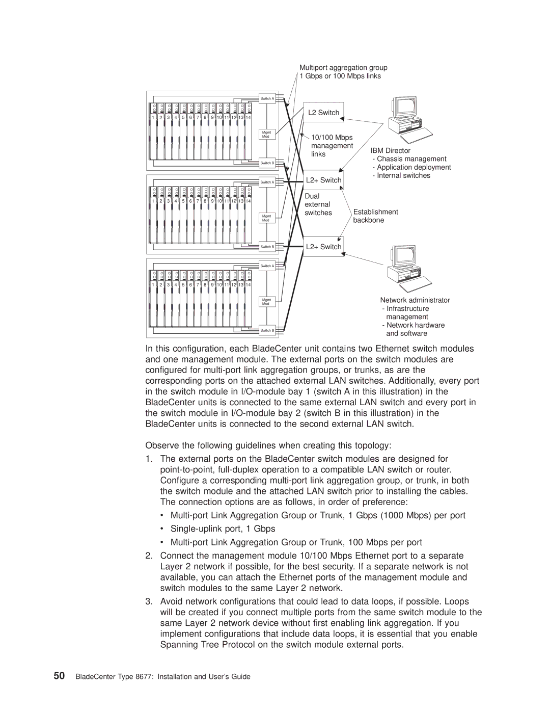
In this configuration, each BladeCenter unit contains two Ethernet switch modules and one management module. The external ports on the switch modules are configured for
Observe the following guidelines when creating this topology:
1.The external ports on the BladeCenter switch modules are designed for
v
v
v
2.Connect the management module 10/100 Mbps Ethernet port to a separate Layer 2 network if possible, for the best security. If a separate network is not available, you can attach the Ethernet ports of the management module and switch modules to the same Layer 2 network.
3.Avoid network configurations that could lead to data loops, if possible. Loops will be created if you connect multiple ports from the same switch module to the same Layer 2 network device without first enabling link aggregation. If you implement configurations that include data loops, it is essential that you enable Spanning Tree Protocol on the switch module external ports.