DTR-5.8 specifications
The Integra DTR-5.8 is a high-performance AV receiver that stands out in the crowded home theater market. Known for its excellent sound quality and advanced features, this model is tailored for audio enthusiasts who demand fidelity and functionality.At the heart of the DTR-5.8 is its robust amplification system, delivering a powerful 105 watts per channel into 8 ohms. This ensures that it can easily drive a variety of speakers, whether for subtle background music or explosive cinematic soundtracks. The receiver is equipped with a 7.2 channel output, allowing users to set up a surround sound system that includes additional subwoofers for deeper bass response.
One of the standout features of the DTR-5.8 is its support for advanced surround sound formats, including Dolby Atmos and DTS:X. These immersive audio technologies create a three-dimensional soundstage, enabling users to experience cinema-like audio at home. The receiver also supports Dolby TrueHD and DTS-HD Master Audio, ensuring high-definition sound quality for Blu-ray and other high-resolution formats.
Regarding connectivity, the Integra DTR-5.8 offers a wide range of options, including multiple HDMI inputs with 4K upscaling capabilities. This allows users to connect a variety of source devices, from game consoles to streaming boxes, with high resolution and ease. The HDMI ports also support HDCP 2.3, ensuring compatibility with the latest content protections.
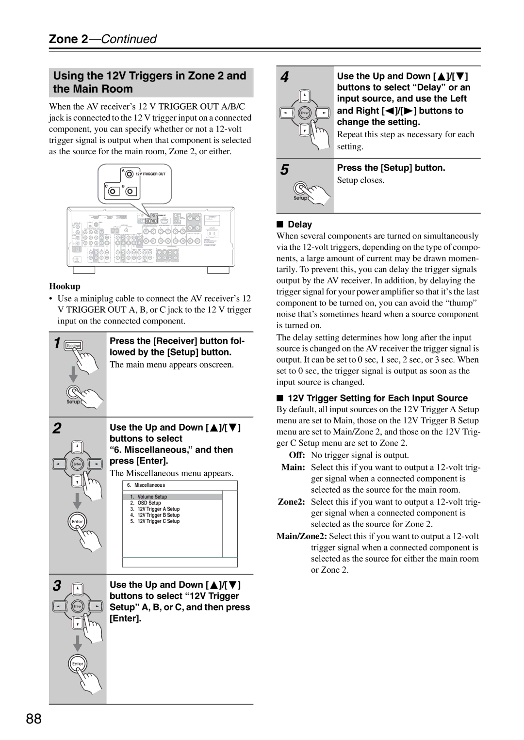
Another key characteristic of the DTR-5.8 is its multi-room audio capability. With built-in Zone 2 audio output, users can enjoy music in different areas of their home simultaneously. Additionally, the receiver supports streaming services like Spotify, Tidal, and Pandora, allowing for seamless access to a vast library of music.
The user interface is intuitive, thanks to an on-screen display and a well-organized remote control. Furthermore, the DTR-5.8 supports network features, including Wi-Fi and Ethernet connectivity for easier setup and access to online content, as well as integration with smart home systems.
In summary, the Integra DTR-5.8 is a feature-rich AV receiver that offers phenomenal sound quality, versatile connectivity options, and support for the latest audio formats. Whether you're a movie buff or a music lover, the DTR-5.8 is designed to enhance your home entertainment experience, making it a top choice for anyone looking to build a premier home theater system.

