DTR-5.9
Important Safety Instructions
Avis
FCC Information for User
Precautions
Power
Supplied Accessories
Contents
Contents
Processing
Features
Amplifier
Connections
Zone 2 Room
Multiroom Capability
Main Room
Getting to Know the AV Receiver
Front Panel
Getting to Know the AV Receiver
Display
Component Video in 1
Rear Panel
Digital in Coaxial 1
Hdmi in 1-4 and OUT
RS232
Sirius antenna on North American model
IR in A/B and OUT
Digital Optical in 1, 2, and OUT
Audio button
Muting button
Button
Sleep button
Using the Remote Controller
Remote Controller
Installing the Batteries
Subwoofer
Connecting Your Speakers
Enjoying Home Theater
Surround back left and right speakers
Speaker Configuration
Connecting Your Speakers
Using Dipole Speakers
Attaching the Speaker Labels
Speaker Connection Precautions
Connecting a Powered Subwoofer
Speaker Color
Connecting the Speaker Cables
Strip about 5/8
Bi-amping Front Speakers
Bi-amping Speaker Hookup
Connecting the AM Loop Antenna
Connecting Antennas
Connecting the Indoor FM Antenna
Attach the FM antenna, as shown American Model
Connecting an Outdoor AM Antenna
Connecting Antennas
Connecting an Outdoor FM Antenna
Using a TV/FM Antenna Splitter
Optical Digital Jacks
Connecting Your Components
About AV Connections
AV Connection Color Coding
Which Connections Should I Use?
Connecting Your Components
Connecting Audio and Video Signals to the AV Receiver
Audio Connection Formats
Video Connection Formats
Video Signal Flow Chart DVD player, etc
TV, projector, etc Signal Selection Example DVD player, etc
TV, projector, etc
Audio Connection
Connecting a TV or Projector
Video Connection
Hint
Connecting a DVD player
DVD player
Hooking Up the Multichannel Input
Connecting a VCR or DVR for Playback
VCR or DVR
Connecting a VCR or DVR for Recording
CBL/SAT in S
Connecting a Game Console
Game Console
Supported Audio Formats
Connecting Components with Hdmi
About Hdmi
About Copyright Protection
Making Hdmi Connections
Video Signals
Audio Signals
Make the video connection a Make the audio connection a
Connecting a Camcorder or Other Device
Connecting a Power Amplifier
CD player
Connecting a CD Player or Turntable
CD Player or Turntable MM with Built-in Phono Preamp Step
CD or turntable
Connecting a Cassette, CDR, MiniDisc, or DAT Recorder
If Your iPod Supports Video
Connecting an RI Dock
Not all iPod models output video
If Your iPod Doesn’t Support Video
Remote Control
Connecting Integra/Onkyo Components
Auto Power On/Standby
Direct Change
Turning On the AV Receiver
Connecting the Power Cord
Do the automatic speaker setup-this is essential
Turning On and Standby
Using Audyssey 2EQ
First Time Setup
Automatic Speaker Setup
Measurement Positions
Following screen appears
First Time Setup
Press Enter
Error Messages
Using a Powered Subwoofer
To Retry the Automatic Speaker Setup
Changing the Speaker Settings Manually
Write Error
Speaker Settings
Sure the appropriate external input is
Hdmi Input Setup
Main menu appears onscreen
Selected on your TV
Press the Receiver button, fol- lowed by the Setup button
Component Video Input Setup
Digital Input Setup
Changing the Input Display
Automatic Audio Input Selection Setup
Basic AV Receiver Operation
Select a listening mode and enjoy
Playing Your AV Components
Start playback on the source component
Common Functions
Setting the Display Brightness
Using the Sleep Timer
Muting the AV Receiver
Displaying Source Information
7Using Headphones
Common Functions
Specifying the Digital Signal Format
Preset Enter
Buttons to select 7. Hardware
AM Frequency Step Setup on some models
Listening to the Radio
Listening to AM/FM Stations
Tuning into AM/FM Radio Stations
Listening to the Radio
Use the Tuner input selector button to select AM or FM
Displaying AM/FM Radio Information
Tuning into Stations by Frequency
Listening mode
Display
Selecting Presets
Deleting Presets
Positioning the Antenna
Setting Up the SiriusConnect Home Tuner
What is Sirius Satellite Radio?
Important Sirius Satellite Radio Information
Use the Up and Down Buttons to select SAT Radio Mode
Setting the Satellite Radio Mode
Mode button, followed by
When you’ve finished, press
Signing Up for Sirius Satellite Radio
Selecting Sirius Satellite Radio Channels
Presetting Sirius Channels
Buttons to select 3. Tuner, and then press Enter
Setup Enter Number buttons
Parental Lock
Changing the PIN Number
Digits in the new PIN number
Old 4-digit PIN number Use the Left and Right
New 4-digit PIN number Use the Left and Right
Confirm the new PIN number by
Displaying Sirius Satellite Radio Information
Positioning the SiriusConnect Home Antenna
Sirius Satellite Radio Messages
Acquiring
RDS Program Types PTY
Using RDS European models only
What is RDS?
Finding Stations by Type PTY
Displaying Radio Text RT
Listening to Traffic News TP
Selecting the Listening Modes
Using the Listening Modes
Selecting with the Remote Controller
Selecting on the AV Receiver
Analog and PCM Sources
Using the Listening Modes
Listening Modes Available for Each Source Format
Dolby Digital and Dolby Digital Plus Sources
DTS Sources
DTS
TrueHD Sources
DTS-HD Sources
DTS Express and DSD Sources
DSD
About the Listening Modes
Onkyo Original DSP Modes
Recording from Different AV Sources
Recording
Recording the Input Source
Multiplex/Mono Settings
Adjusting the Listening Modes
Using the Audio Adjust Settings
PLIIx/Neo6 Settings
Theater-Dimensional Setting
Adjusting the Listening Modes
Dolby EX Settings
Late Night Function
Using the Audio Settings
Tone Control Settings
CinemaFILTER
Music Optimizer
Audyssey Dynamic EQ
Speaker Levels
Sync
Listening Mode Presets
Advanced Setup
Speaker Setup
Select a crossover frequency
Advanced Setup
Low-Pass Filter for the LFE Channel
Use the Down button to
Double Bass
Speaker Distance
Pink noise test tone is output by the front left speaker
Equalizer Settings
Setup menu closes
Source Setup
IntelliVolume
OSD Setup
Miscellaneous Setup
Volume Setup
Hardware Setup
Remote Control
Analog Multich
Zone
Tuner
Color
Audio TV Out
Lip Sync
Control
Lock Setup
Network
Connecting Your Zone 2 Speakers to an Amp in Zone
Connecting Zone
Connecting Your Zone 2 Speakers Directly to the AV receiver
Zone
Buttons to select 2. Zone2,
Powered Zone 2 Setting
If you’ve connected your Zone 2 speakers to the AV
Zone2
Zone 2 Out Settings
Enter Setup
Input
Controlling Zone 2 from the AV receiver
Using Zone
Controlling Zone 2 with the Remote Controller
Adjusting the Balance of Zone
Adjusting the Volume of Zone
Adjusting the Tone of Zone
Muting Zone
Miscellaneous, and then press Enter
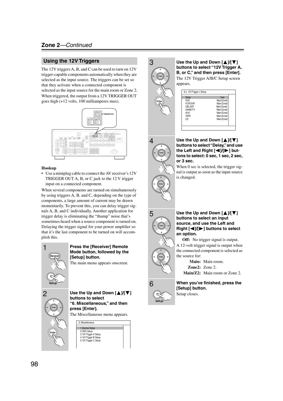
Using the 12V Triggers
When you’ve finished, press the Setup button
Using a Multiroom Kit with Other Components
Using a Multiroom Kit with a Cabinet
Using a Multiroom Kit with Zone
Controlling Other Components
Preprogrammed Remote Control Codes
Entering Remote Control Codes
100
101
Resetting the Remote Controller
Resetting the Remote Mode Buttons
Controlling Other Components
102
Controlling a TV
103
Controlling a DVD Player, or DVD Recorder
Controlling a VCR or DVR
Play Mode button
104
Previous button
105
Controlling a Satellite Receiver or Cable Receiver
Search button
106
Controlling a CD Player, CD Recorder, or MD Player
Disc +/- button
107
Controlling an RI Dock
108
Controlling a Cassette Recorder
Troubleshooting
109
Troubleshooting
110
111
112
Important Note Regarding Video Playback
Specifications
113
Output
Video Resolution Chart
114
Menu Map
Onscreen Setup Menus
115
Main menu
116
Onkyo Corporation