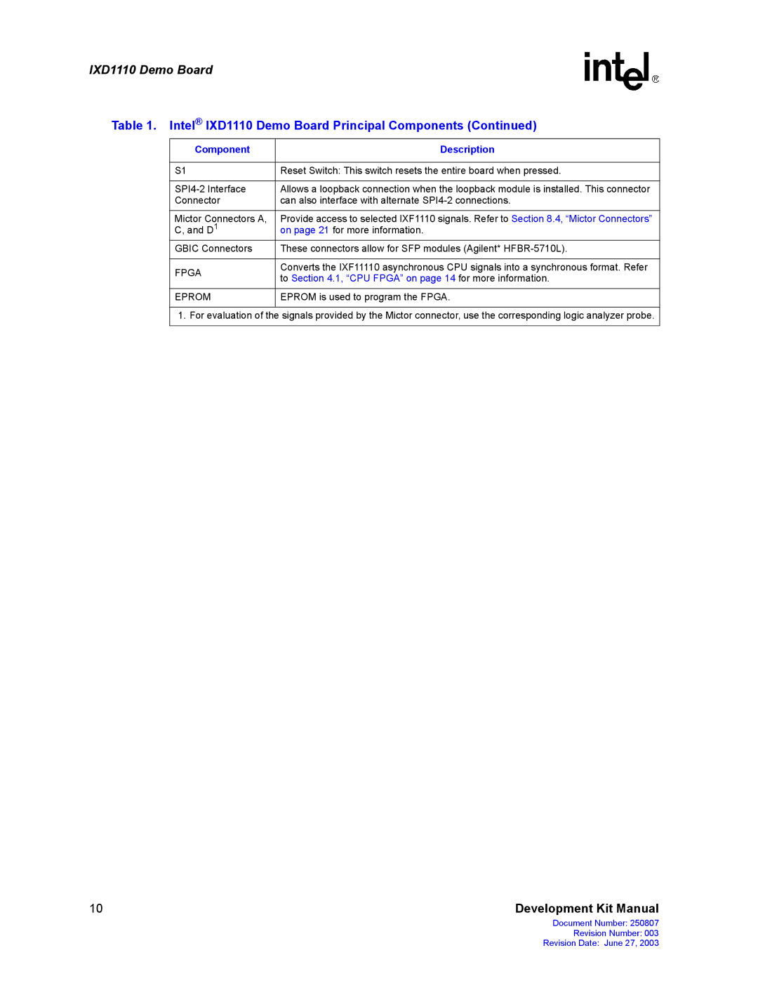
IXD1110 specifications
The Intel IXD1110 is an advanced integrated circuit that serves as a highly efficient and versatile solution for various communication and data processing applications. Built on Intel's cutting-edge technology, the IXD1110 showcases enhanced performance characteristics tailored for modern industrial and embedded systems.One of the most notable features of the IXD1110 is its robust processing capability. Designed to support high-speed data transfer, this device operates with a clock frequency of up to 500 MHz. Such a high processing speed ensures that the IXD1110 can handle data-heavy applications with ease, making it an ideal choice for real-time data processing tasks.
In terms of connectivity, the IXD1110 boasts multiple communication interfaces. It supports Ethernet, SPI, and I2C protocols, allowing seamless integration into various system architectures. The Ethernet interface ensures high-bandwidth connectivity, giving developers the flexibility to connect the IXD1110 to both wired and wireless networks. This opens up possibilities for IoT (Internet of Things) applications, where reliable and fast communication is critical.
Another standout feature of the IXD1110 is its low-power consumption, which is a significant consideration for embedded systems and battery-powered devices. Intel has implemented advanced power management technologies in the IXD1110, enabling it to operate efficiently while minimizing energy usage. This characteristic not only extends the lifespan of the devices it powers but also reduces overall operational costs.
The IXD1110 also includes advanced security features, catering to the growing demand for secure processing in connected devices. Integrated hardware security mechanisms help safeguard against vulnerabilities and attacks, ensuring data integrity and protecting sensitive information.
Additionally, the IXD1110 is designed for scalability, allowing developers to adapt the device to a wide range of applications, from automotive systems to industrial automation. Its flexible architecture accommodates future upgrades and enhancements, making it a long-term investment for companies looking to future-proof their systems.
In conclusion, the Intel IXD1110 stands out with its high processing speeds, versatile connectivity options, low power consumption, advanced security features, and scalability. These attributes make it a compelling choice for organizations looking to leverage cutting-edge technology in their communication and data processing systems. As industries continue to evolve towards greater connectivity and automation, the IXD1110 is positioned as a key enabler in this technological transformation.

