mPGA604 specifications
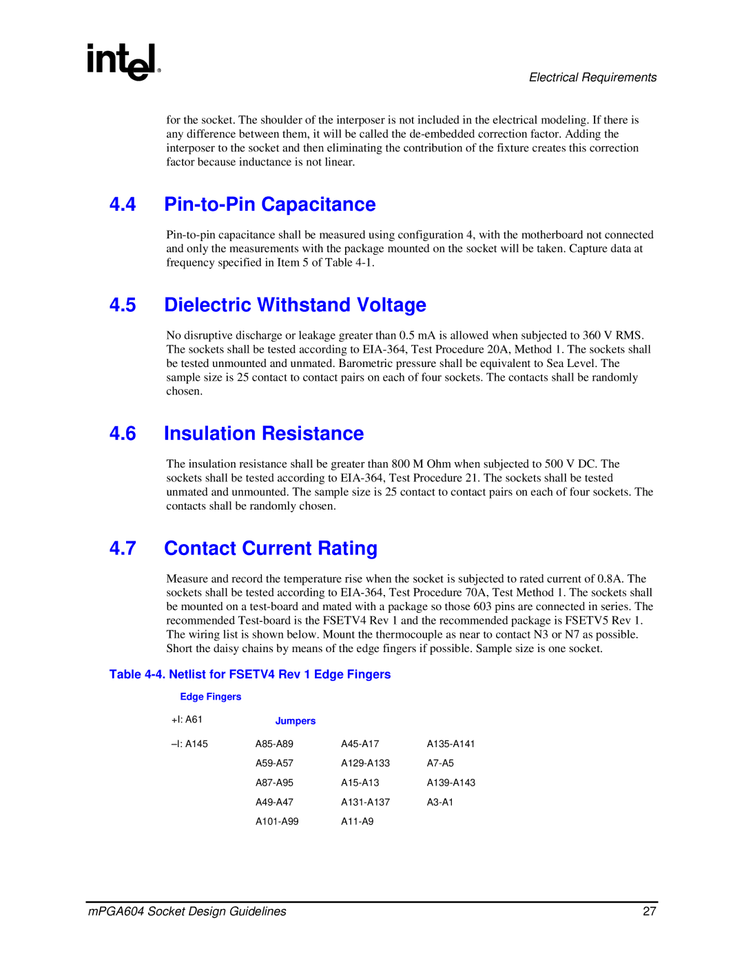
The Intel mPGA604 is a prominent socket specification that has become synonymous with performance in the realm of computing. Designed primarily for users requiring substantial processing power, the mPGA604 socket hosts a variety of Intel processors, notably including the Pentium II and Pentium III series, along with Xeon chips in various configurations. The integration of this technology has facilitated the development of powerful computing machines aimed at both enterprise and individual users.One of the main features of the mPGA604 socket is its pin grid array configuration, which offers a secure mount for processors. This design allows for efficient heat dissipation and improved electrical connectivity, essential for maintaining the performance of high-end CPUs. The mPGA604 uses 604 pins that create a robust connection, allowing for stable and consistent data transfer between the CPU and the motherboard.
Another significant characteristic of mPGA604 is its support for a range of processor clock speeds and voltage specifications. The socket is integrated with technologies like Intel's SpeedStep, which dynamically adjusts the processor's voltage and frequency according to the workload. This helps in managing power consumption and heat generation, which is critical for longevity and reliability in computing systems.
The mPGA604 also introduces features like Multiple Processor support, enabling systems to leverage dual or even quad-processor configurations effectively. This capability significantly enhances computational performance, making the socket an excellent choice for server applications and high-performance workstations.
Moreover, the socket supports advanced memory technologies, such as SDRAM and RDIMM, allowing for flexible memory configurations tailored to specific performance needs. The ability to utilize dual-channel memory architectures maximizes throughput, facilitating improved application performance and system responsiveness.
In conclusion, the Intel mPGA604 socket represents a well-engineered solution catering to users seeking enhanced processing power and efficiency. Its combination of a robust pin configuration, power management technologies, multiple processor support, and compatibility with advanced memory standards makes it an indispensable choice for performance-driven computing solutions in both personal and professional environments. As computing demands continue to evolve, the mPGA604 stands as a testament to Intel's commitment to innovation and adaptability in the technology landscape.

