Maintaining Your Server
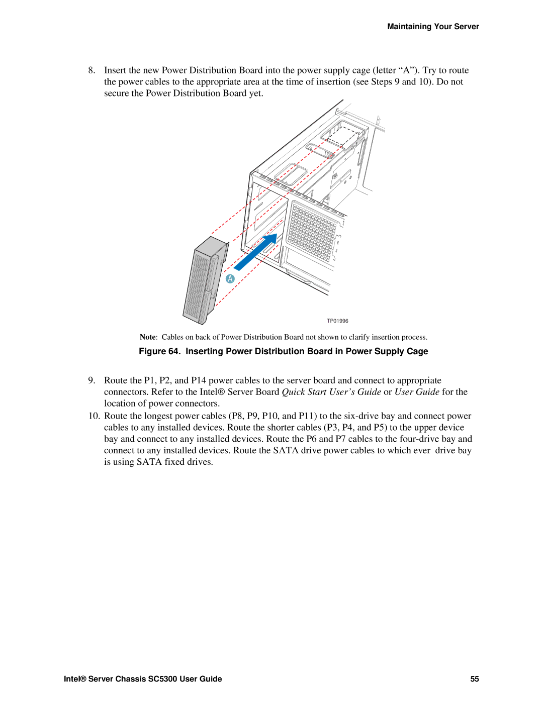
8.Insert the new Power Distribution Board into the power supply cage (letter “A”). Try to route the power cables to the appropriate area at the time of insertion (see Steps 9 and 10). Do not secure the Power Distribution Board yet.
A
TP01996
Note: Cables on back of Power Distribution Board not shown to clarify insertion process.
Figure 64. Inserting Power Distribution Board in Power Supply Cage
9.Route the P1, P2, and P14 power cables to the server board and connect to appropriate connectors. Refer to the Intel® Server Board Quick Start User’s Guide or User Guide for the location of power connectors.
10.Route the longest power cables (P8, P9, P10, and P11) to the
Intel® Server Chassis SC5300 User Guide | 55 |