Introduction
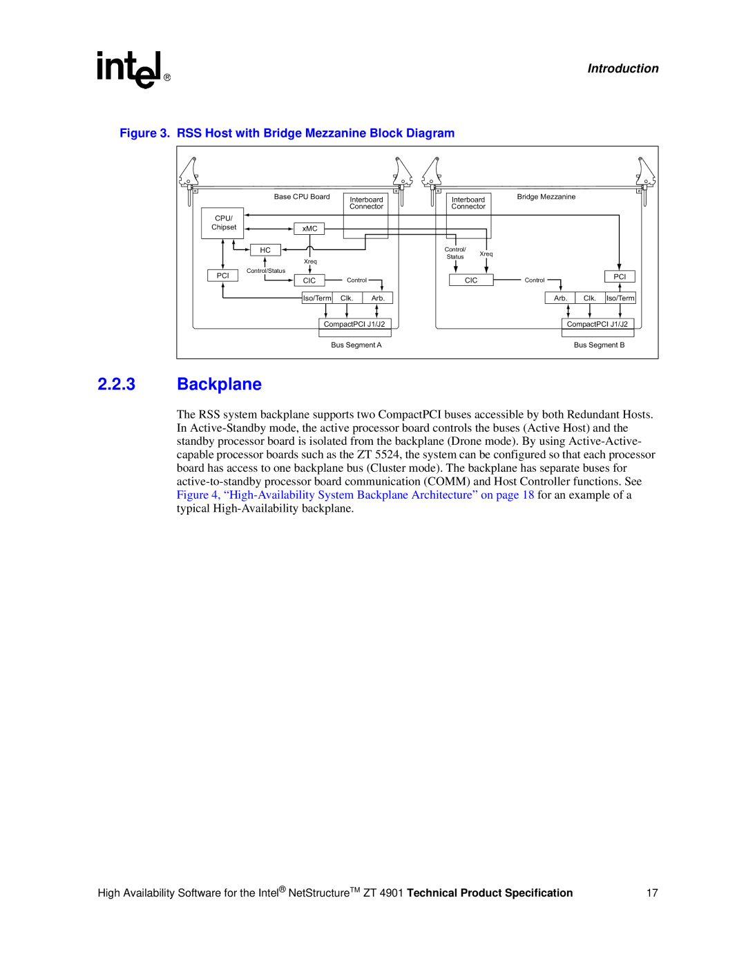
Figure 3. RSS Host with Bridge Mezzanine Block Diagram
|
| Base CPU Board | Interboard | Interboard | Bridge Mezzanine |
| |||
|
|
|
|
|
| ||||
|
|
| Connector | Connector |
|
|
| ||
| CPU/ |
|
|
|
|
|
|
|
|
| Chipset | xMC |
|
|
|
|
|
|
|
|
| HC |
|
| Control/ | Xreq |
|
|
|
|
|
|
|
| Status |
|
|
| |
|
| Xreq |
|
|
|
|
|
| |
|
|
|
|
|
|
|
|
| |
| PCI | Control/Status |
|
|
|
|
|
|
|
| CIC | Control |
| CIC |
| Control |
| PCI | |
|
|
|
|
|
| ||||
|
| Iso/Term | Clk. | Arb. |
|
| Arb. | Clk. | Iso/Term |
|
| CompactPCI J1/J2 |
|
| CompactPCI J1/J2 | ||||
|
|
| Bus Segment A |
|
|
| Bus Segment B | ||
2.2.3 | Backplane |
|
|
|
|
|
|
| |
The RSS system backplane supports two CompactPCI buses accessible by both Redundant Hosts. In
High Availability Software for the Intel® NetStructureTM ZT 4901 Technical Product Specification | 17 |