PROCEDURE 3 | BACK | |
|
|
|
B A C K
WARNING
The back canes MUST be fastened securely to the seat frame BEFORE using the wheelchair.
DO NOT overtighten hex bolts. Overtightening hex bolts will prohibit the free movement of the back canes, preventing the back canes from locking prop- erly.
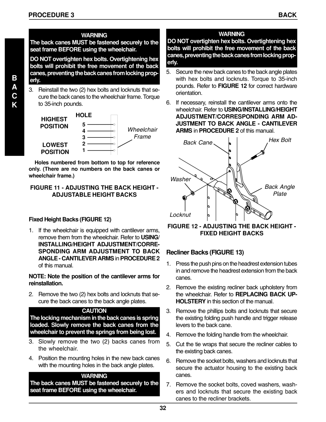
3.Reinstall the two (2) hex bolts and locknuts that se- cure the back canes to the wheelchair frame. Torque to
HIGHEST | HOLE |
|
5 |
| |
POSITION | Wheelchair | |
| 4 | |
| 3 | Frame |
LOWEST | 2 |
|
POSITION | 1 |
|
✪Holes numbered from bottom to top for reference only. (There are no numbers on the back canes or wheelchair frame.)
FIGURE 11 - ADJUSTING THE BACK HEIGHT -
ADJUSTABLE HEIGHT BACKS
Fixed Height Backs (FIGURE 12)
1.If the wheelchair is equipped with cantilever arms, remove them from the wheelchair. Refer to USING/
INSTALLING/HEIGHT ADJUSTMENT/CORRE- SPONDING ARM ADJUSTMENT TO BACK ANGLE - CANTILEVER ARMS in PROCEDURE 2 of this manual.
NOTE: Note the position of the cantilever arms for reinstallation.
2.Remove the two (2) hex bolts and locknuts that se- cure the back canes to the back angle plates.
CAUTION
The locking mechanism in the back canes is spring loaded. Slowly remove the back canes from the wheelchair to prevent the springs from being lost.
3.Slowly remove the two (2) backs canes from the wheelchair.
4.Position the mounting holes in the new back canes with the mounting holes in the back angle plates.
WARNING
The back canes MUST be fastened securely to the seat frame BEFORE using the wheelchair.
WARNING
DO NOT overtighten hex bolts. Overtightening hex bolts will prohibit the free movement of the back canes, preventing the back canes from locking prop- erly.
5.Secure the new back canes to the back angle plates with hex bolts and locknuts. Torque to
6.If necessary, reinstall the cantilever arms onto the wheelchair. Refer to USING/INSTALLING/HEIGHT
ADJUSTMENT/CORRESPONDING ARM AD- JUSTMENT TO BACK ANGLE - CANTILEVER ARMS in PROCEDURE 2 of this manual.
Back Cane | Hex Bolt |
|
Washer
Back Angle
Plate
Locknut
FIGURE 12 - ADJUSTING THE BACK HEIGHT -
FIXED HEIGHT BACKS
Recliner Backs (FIGURE 13)
1.Press the push pins on the headrest extension tubes in and remove the headrest extension from the back canes.
2.Remove the existing recliner back upholstery from the wheelchair. Refer to REPLACING BACK UP- HOLSTERY in this section of the manual.
3.Remove the phillips bolts and locknuts that secure the existing folding push handle and trigger release levers to the back cane.
4.Remove the folding handle from the wheelchair.
5.Cut the tie wraps that secure the recliner cables to the existing back canes.
6.Remove the socket bolts, washers and locknuts that secure the actuator housing to the existing back canes.
7.Remove the socket bolts, coved washers, wash- ers and locknuts that secure the existing back canes to the recliner brackets.
32
