PROCEDURE 3 | BACK | |
|
|
|
B A C K
CHANGING THE BACK ANGLE
WARNING
The seat height, seat depth, back angle, seating sys- tem, size and position of the rear wheels, as well as the user condition directly relate to the stability of the wheelchair. Any change to one (1) or any combi- nation of the seven (7) may cause the wheelchair to decrease in stability. These adjustments MUST be performed by an authorized dealer or qualified tech- nician.
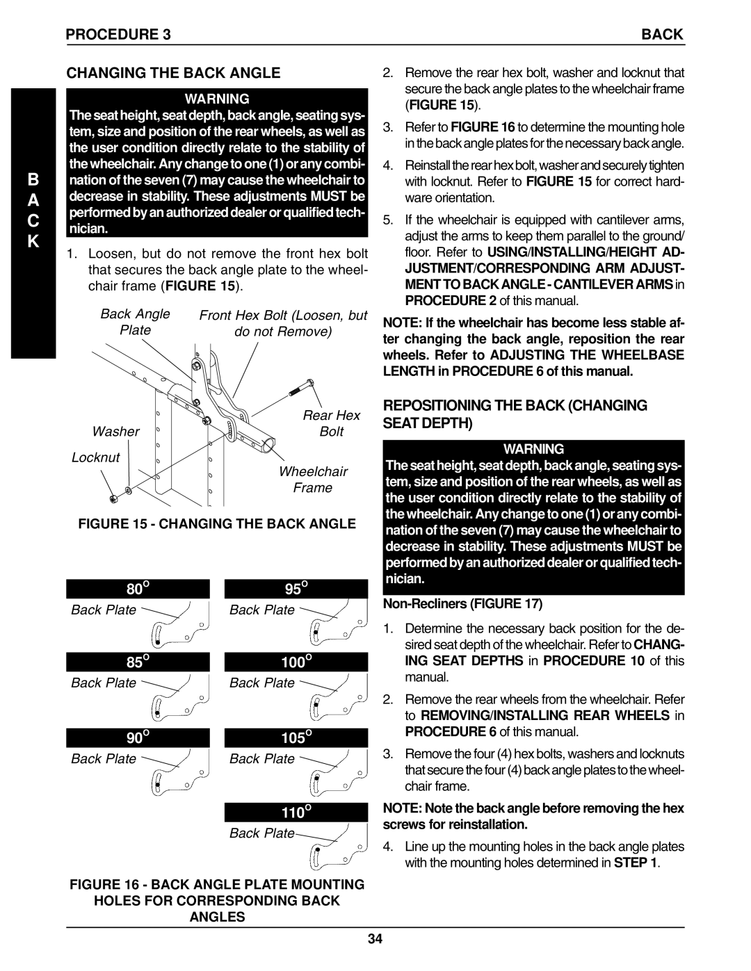
1.Loosen, but do not remove the front hex bolt that secures the back angle plate to the wheel- chair frame (FIGURE 15).
Back Angle | Front Hex Bolt (Loosen, but |
Plate | do not Remove) |
| Rear Hex |
Washer | Bolt |
Locknut
Wheelchair
Frame
FIGURE 15 - CHANGING THE BACK ANGLE
2.Remove the rear hex bolt, washer and locknut that secure the back angle plates to the wheelchair frame (FIGURE 15).
3.Refer to FIGURE 16 to determine the mounting hole in the back angle plates for the necessary back angle.
4.Reinstall the rear hex bolt, washer and securely tighten with locknut. Refer to FIGURE 15 for correct hard- ware orientation.
5.If the wheelchair is equipped with cantilever arms, adjust the arms to keep them parallel to the ground/ floor. Refer to USING/INSTALLING/HEIGHT AD-
JUSTMENT/CORRESPONDING ARM ADJUST- MENT TO BACK ANGLE - CANTILEVER ARMS in PROCEDURE 2 of this manual.
NOTE: If the wheelchair has become less stable af- ter changing the back angle, reposition the rear wheels. Refer to ADJUSTING THE WHEELBASE LENGTH in PROCEDURE 6 of this manual.
REPOSITIONING THE BACK (CHANGING SEAT DEPTH)
WARNING
The seat height, seat depth, back angle, seating sys- tem, size and position of the rear wheels, as well as the user condition directly relate to the stability of the wheelchair. Any change to one (1) or any combi- nation of the seven (7) may cause the wheelchair to decrease in stability. These adjustments MUST be performed by an authorized dealer or qualified tech- nician.
80O
Back Plate 
85O
Back Plate ![]()
90O
Back Plate ![]()
95O
Back Plate ![]()
100O
Back Plate ![]()
105O
Back Plate ![]()
110O
Back Plate
Non-Recliners (FIGURE 17)
1.Determine the necessary back position for the de- sired seat depth of the wheelchair. Refer to CHANG- ING SEAT DEPTHS in PROCEDURE 10 of this manual.
2.Remove the rear wheels from the wheelchair. Refer to REMOVING/INSTALLING REAR WHEELS in PROCEDURE 6 of this manual.
3.Remove the four (4) hex bolts, washers and locknuts that secure the four (4) back angle plates to the wheel- chair frame.
NOTE: Note the back angle before removing the hex screws for reinstallation.
4.Line up the mounting holes in the back angle plates with the mounting holes determined in STEP 1.
FIGURE 16 - BACK ANGLE PLATE MOUNTING
HOLES FOR CORRESPONDING BACK
ANGLES
34