PROCEDURE 1 | FRONT RIGGINGS |
F
R O N T
R
I
G G I N G S
This Procedure includes the following:
Installing Footrests
Adjusting Footrest Height
Installing
Installing Elevating Legrests
Raising/Lowering Elevating Legrests and/or Adjusting Calfpads
Installing/Adjusting Adjustable Angle
Replacing Sector Block
Optional Footrest Accessories
WARNING
After adjustments, and before use, make sure all attaching hardware is securely tightened.
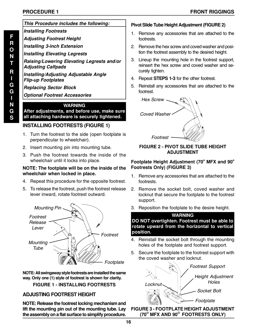
INSTALLING FOOTRESTS (FIGURE 1)
1.Turn the footrest to the side (open footplate is perpendicular to wheelchair).
2.Insert mounting pin into mounting tube.
3.Push the footrest towards the inside of the wheelchair until it locks into place.
NOTE: The footplate will be on the inside of the wheelchair when locked in place.
4.Repeat this procedure for the opposite footrest.
5.To release the footrest, push the footrest release lever inward, rotate footrest outward.
Mounting Pin
Footrest
Release
Lever
Footrest
Mounting ![]()
Tube
Footplate
NOTE: All swingaway style footrests are installed the same way. Only one (1) style of footrest is shown for clarity.
FIGURE 1 - INSTALLING FOOTRESTS
ADJUSTING FOOTREST HEIGHT
NOTE: Release the footrest locking mechanism and lift the mounting pin out of the mounting tube. Lay the assembly on a flat surface to simplify procedure.
Pivot Slide Tube Height Adjustment (FIGURE 2)
1.Remove any accessories that are attached to the footrests.
2.Remove the hex screw and coved washer and posi- tion the footrest assembly to the desired height.
3.Lineup the mounting hole in the footrest support, reinsert the hex screw and coved washer and se- curely tighten.
4.Repeat STEPS
5.Reinstall any accessories that are attached to the footrest.
Hex Screw
Coved Washer
Footrest
FIGURE 2 - PIVOT SLIDE TUBE HEIGHT
ADJUSTMENT
Footplate Height Adjustment (70o MFX and 90o Footrests Only) (FIGURE 3)
1.Remove any accessories that are attached to the footrests.
2.Remove the socket bolt, coved washer and locknut that secure the footplate to the footrest support.
3.Reposition the footplate to the desire height.
WARNING
DO NOT overtighten. Footrest must be able to rotate upward from the horizontal to vertical position.
4.Reinstall the socket bolt through the mounting holes of the footplate and footrest support.
5.Secure the footplate to the footrest support with the coved washer and locknut.
| Footrest Support |
| Height Adjustment |
Locknut | Holes |
| |
| Socket Bolt |
| Footplate |
FIGURE 3 - FOOTPLATE HEIGHT ADJUSTMENT
(70O MFX AND 90O FOOTRESTS ONLY)
16