PROCEDURE 2 | ARMS | |
|
|
|
A R M S
This Procedure Includes the Following:
Installing the "T" Arm Sockets
Installing/Removing the "T" Arms
Adjusting the "T" Arms
Adjusting the Transfer Assists and/or Side Guards - "T" Arms
Replacing the Locking Lever - "T" Arms
Using/Installing/Height Adjustment/Corresponding Adjustment to Back Angle - Cantilever Arms
Replacing/Repositioning the Locking
Mechanism in the Cantilever Arm
Arm Pad Depth Adjustment/Replacement - Cantilever Arms
Installing Fabric Clothing Guards
Installing Rigid Side Guards
Adjusting Conventional Arm Height, Removing or Replacing Conventional Arms
Replacing Armrest Pads
Repositioning the Conventional Arms
WARNING
NEVER try to lift or tip the wheelchair by cantilever arms or "T" arms, serious injury can occur.
After adjustments and before use, make sure all at- taching hardware is securely tightened.
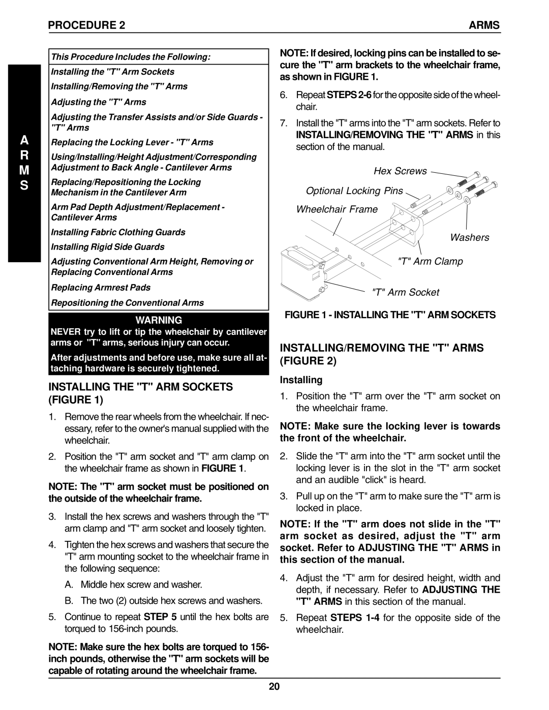
NOTE: If desired, locking pins can be installed to se- cure the "T" arm brackets to the wheelchair frame, as shown in FIGURE 1.
6.Repeat STEPS
7.Install the "T" arms into the "T" arm sockets. Refer to INSTALLING/REMOVING THE "T" ARMS in this section of the manual.
Hex Screws
Optional Locking Pins
Wheelchair Frame
Washers
"T" Arm Clamp
"T" Arm Socket
FIGURE 1 - INSTALLING THE "T" ARM SOCKETS
INSTALLING/REMOVING THE "T" ARMS (FIGURE 2)
INSTALLING THE "T" ARM SOCKETS (FIGURE 1)
1.Remove the rear wheels from the wheelchair. If nec- essary, refer to the owner's manual supplied with the wheelchair.
2.Position the "T" arm socket and "T" arm clamp on the wheelchair frame as shown in FIGURE 1.
NOTE: The "T" arm socket must be positioned on the outside of the wheelchair frame.
3.Install the hex screws and washers through the "T" arm clamp and "T" arm socket and loosely tighten.
4.Tighten the hex screws and washers that secure the "T" arm mounting socket to the wheelchair frame in the following sequence:
A.Middle hex screw and washer.
B.The two (2) outside hex screws and washers.
5.Continue to repeat STEP 5 until the hex bolts are torqued to
NOTE: Make sure the hex bolts are torqued to 156- inch pounds, otherwise the "T" arm sockets will be capable of rotating around the wheelchair frame.
Installing
1.Position the "T" arm over the "T" arm socket on the wheelchair frame.
NOTE: Make sure the locking lever is towards the front of the wheelchair.
2.Slide the "T" arm into the "T" arm socket until the locking lever is in the slot in the "T" arm socket and an audible "click" is heard.
3.Pull up on the "T" arm to make sure the "T" arm is locked in place.
NOTE: If the "T" arm does not slide in the "T" arm socket as desired, adjust the "T" arm socket. Refer to ADJUSTING THE "T" ARMS in this section of the manual.
4.Adjust the "T" arm for desired height, width and depth, if necessary. Refer to ADJUSTING THE "T" ARMS in this section of the manual.
5.Repeat STEPS
20
