PROCEDURE 6 | REAR WHEELS |
R E A R
W
H
E
E
L
S
5.Reinstall rear wheel to the wheelchair. Refer to REMOVING/INSTALLING REAR WHEELS in this section of the manual.
6.If the locking pins of the
7.Repeat the procedure for the opposite rear wheel if necessary.
INSTALLING PROJECTION HANDRIMS
NOTE: The following procedures will work for any type of projection handrim.
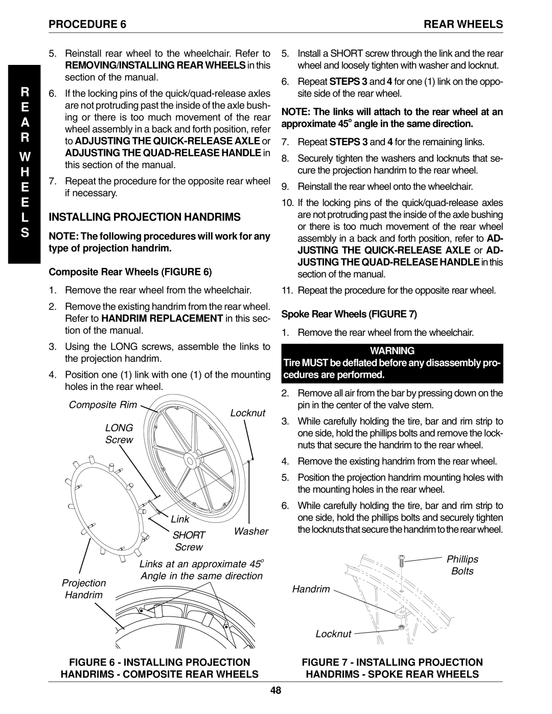
Composite Rear Wheels (FIGURE 6)
1.Remove the rear wheel from the wheelchair.
2.Remove the existing handrim from the rear wheel. Refer to HANDRIM REPLACEMENT in this sec- tion of the manual.
3.Using the LONG screws, assemble the links to the projection handrim.
4.Position one (1) link with one (1) of the mounting holes in the rear wheel.
Composite Rim
Locknut
LONG
Screw
Link
SHORT Washer
Screw
Links at an approximate 45o
Angle in the same direction
Projection
Handrim
5.Install a SHORT screw through the link and the rear wheel and loosely tighten with washer and locknut.
6.Repeat STEPS 3 and 4 for one (1) link on the oppo- site side of the rear wheel.
NOTE: The links will attach to the rear wheel at an approximate 45o angle in the same direction.
7.Repeat STEPS 3 and 4 for the remaining links.
8.Securely tighten the washers and locknuts that se- cure the projection handrim to the rear wheel.
9.Reinstall the rear wheel onto the wheelchair.
10.If the locking pins of the
11.Repeat the procedure for the opposite rear wheel.
Spoke Rear Wheels (FIGURE 7)
1. Remove the rear wheel from the wheelchair.
WARNING
Tire MUST be deflated before any disassembly pro- cedures are performed.
2.Remove all air from the bar by pressing down on the pin in the center of the valve stem.
3.While carefully holding the tire, bar and rim strip to one side, hold the phillips bolts and remove the lock- nuts that secure the handrim to the rear wheel.
4.Remove the existing handrim from the rear wheel.
5.Position the projection handrim mounting holes with the mounting holes in the rear wheel.
6.While carefully holding the tire, bar and rim strip to one side, hold the phillips bolts and securely tighten the locknuts that secure the handrim to the rear wheel.
Phillips
Bolts
Handrim
Locknut
FIGURE 6 - INSTALLING PROJECTION | FIGURE 7 - INSTALLING PROJECTION |
HANDRIMS - COMPOSITE REAR WHEELS | HANDRIMS - SPOKE REAR WHEELS |
48