Section 2: Installation and Setup
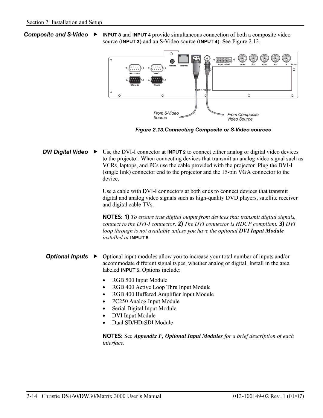
Composite and
| Figure 2.13.Connecting Composite or |
DVI Digital Video | f Use the |
| to the projector. When connecting devices that transmit an analog video signal such as |
| VCRs, laptops, and PCs use the cable provided with the projector. Plug the |
| (single link) connector end to the projector and the |
| device. |
| Use a cable with |
| digital and analog video signals such as |
| and digital cable TVs. |
| NOTES: 1) To ensure true digital output from devices that transmit digital signals, |
| connect to the |
| loop through is not available unless you have the optional DVI Input Module |
| installed at INPUT 5. |
Optional Inputs | f Optional input modules allow you to increase your total number of inputs and/or |
| accommodate different signal types, whether analog or digital. Install in the area |
| labeled INPUT 5. Options include: |
| • RGB 500 Input Module |
| • RGB 400 Active Loop Thru Input Module |
| • RGB 400 Buffered Amplifier Input Module |
| • PC250 Analog Input Module |
| • Serial Digital Input Module |
| • DVI Input Module |
| • Dual |
| NOTES: See Appendix F, Optional Input Modules for a brief description of each |
| interface. |