Section 3: Operation
black and white are known to be at opposite edges of the image, you can watch these isolated areas while adjusting individual blacklevels and input drives until both black and white edges are just visible and distinguished from neighboring pixels. Images from this source will then display correct blacks and whites without crushing.
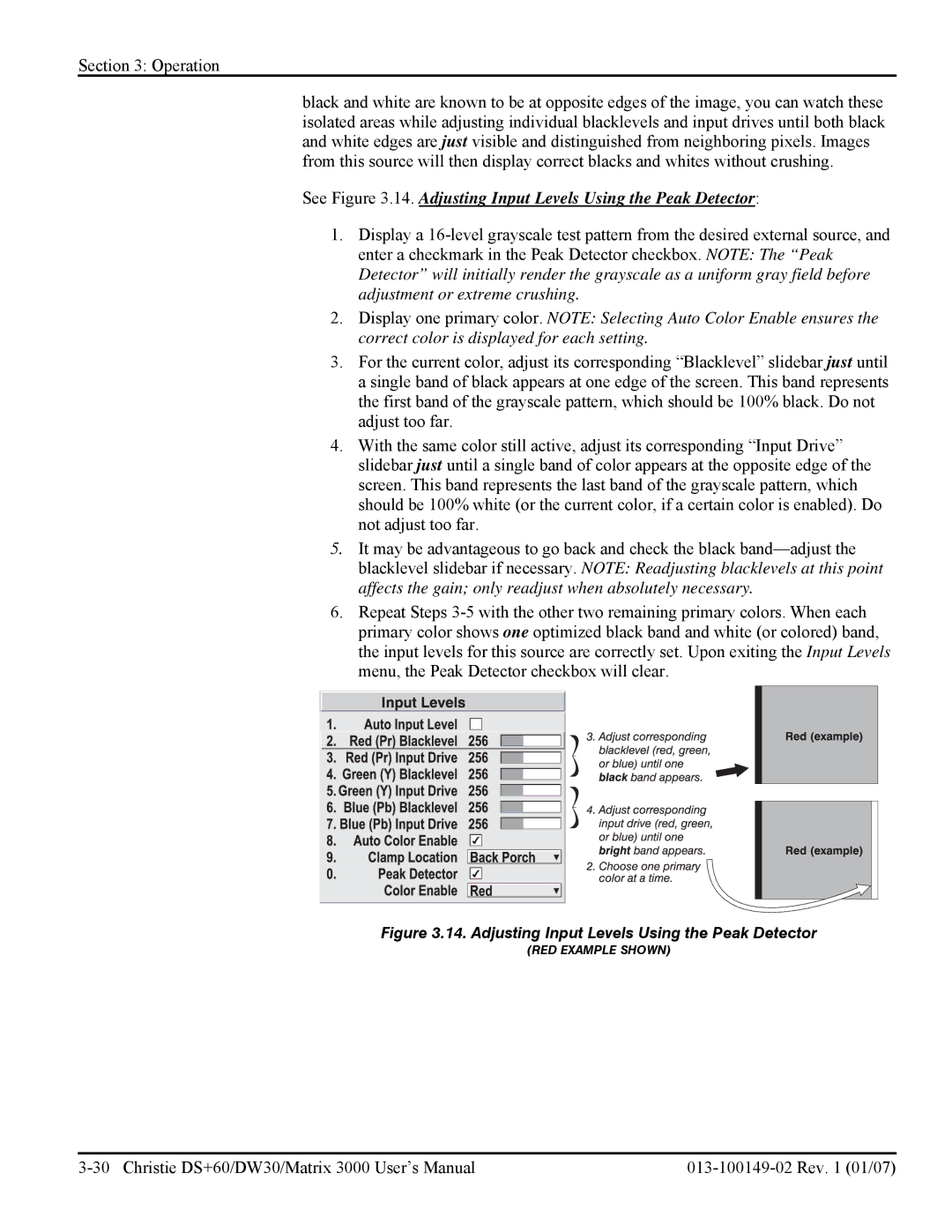
See Figure 3.14. Adjusting Input Levels Using the Peak Detector:
1.Display a
2.Display one primary color. NOTE: Selecting Auto Color Enable ensures the correct color is displayed for each setting.
3.For the current color, adjust its corresponding “Blacklevel” slidebar just until a single band of black appears at one edge of the screen. This band represents the first band of the grayscale pattern, which should be 100% black. Do not adjust too far.
4.With the same color still active, adjust its corresponding “Input Drive” slidebar just until a single band of color appears at the opposite edge of the screen. This band represents the last band of the grayscale pattern, which should be 100% white (or the current color, if a certain color is enabled). Do not adjust too far.
5.It may be advantageous to go back and check the black
6.Repeat Steps
Figure 3.14. Adjusting Input Levels Using the Peak Detector
(RED EXAMPLE SHOWN)