Section 2: Installation and Setup
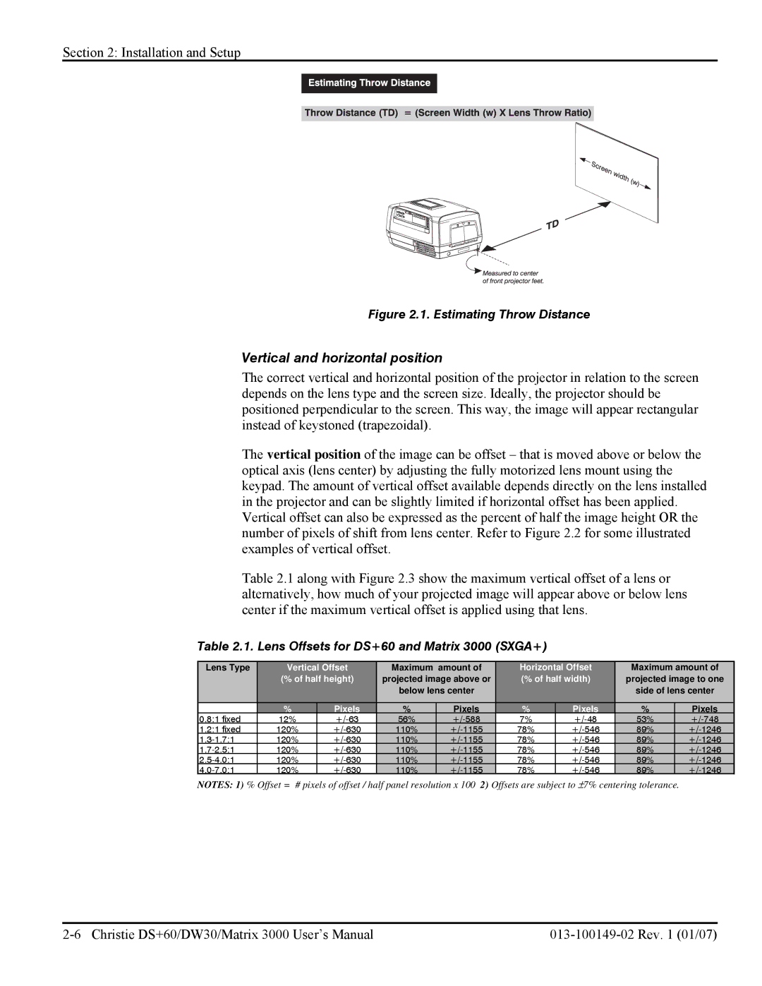
Figure 2.1. Estimating Throw Distance
Vertical and horizontal position
The correct vertical and horizontal position of the projector in relation to the screen depends on the lens type and the screen size. Ideally, the projector should be positioned perpendicular to the screen. This way, the image will appear rectangular instead of keystoned (trapezoidal).
The vertical position of the image can be offset – that is moved above or below the optical axis (lens center) by adjusting the fully motorized lens mount using the keypad. The amount of vertical offset available depends directly on the lens installed in the projector and can be slightly limited if horizontal offset has been applied. Vertical offset can also be expressed as the percent of half the image height OR the number of pixels of shift from lens center. Refer to Figure 2.2 for some illustrated examples of vertical offset.
Table 2.1 along with Figure 2.3 show the maximum vertical offset of a lens or alternatively, how much of your projected image will appear above or below lens center if the maximum vertical offset is applied using that lens.
Table 2.1. Lens Offsets for DS+60 and Matrix 3000 (SXGA+)
Lens Type | Vertical Offset | Maximum amount of | Horizontal Offset | Maximum amount of | ||||
| (% of half height) | projected image above or | (% of half width) | projected image to one | ||||
|
|
| below lens center |
|
| side of lens center | ||
|
|
|
|
|
|
|
|
|
| % | Pixels | % | Pixels | % | Pixels | % | Pixels |
0.8:1 fixed | 12% | 56% | 7% | 53% | ||||
1.2:1 fixed | 120% | 110% | 78% | 89% | ||||
120% | 110% | 78% | 89% | |||||
120% | 110% | 78% | 89% | |||||
120% | 110% | 78% | 89% | |||||
120% | 110% | 78% | 89% | |||||
NOTES: 1) % Offset = # pixels of offset / half panel resolution x 100 2) Offsets are subject to ±7% centering tolerance.