Section 3: Operation
Main Functions
Use standard edge blending controls to set the precise width, shape and midpoint you need to blend overlapping edges together smoothly.
Blend Width determines how much area is used for blending along an overlapping edge. Slidebar values represent the number of
Ranges:
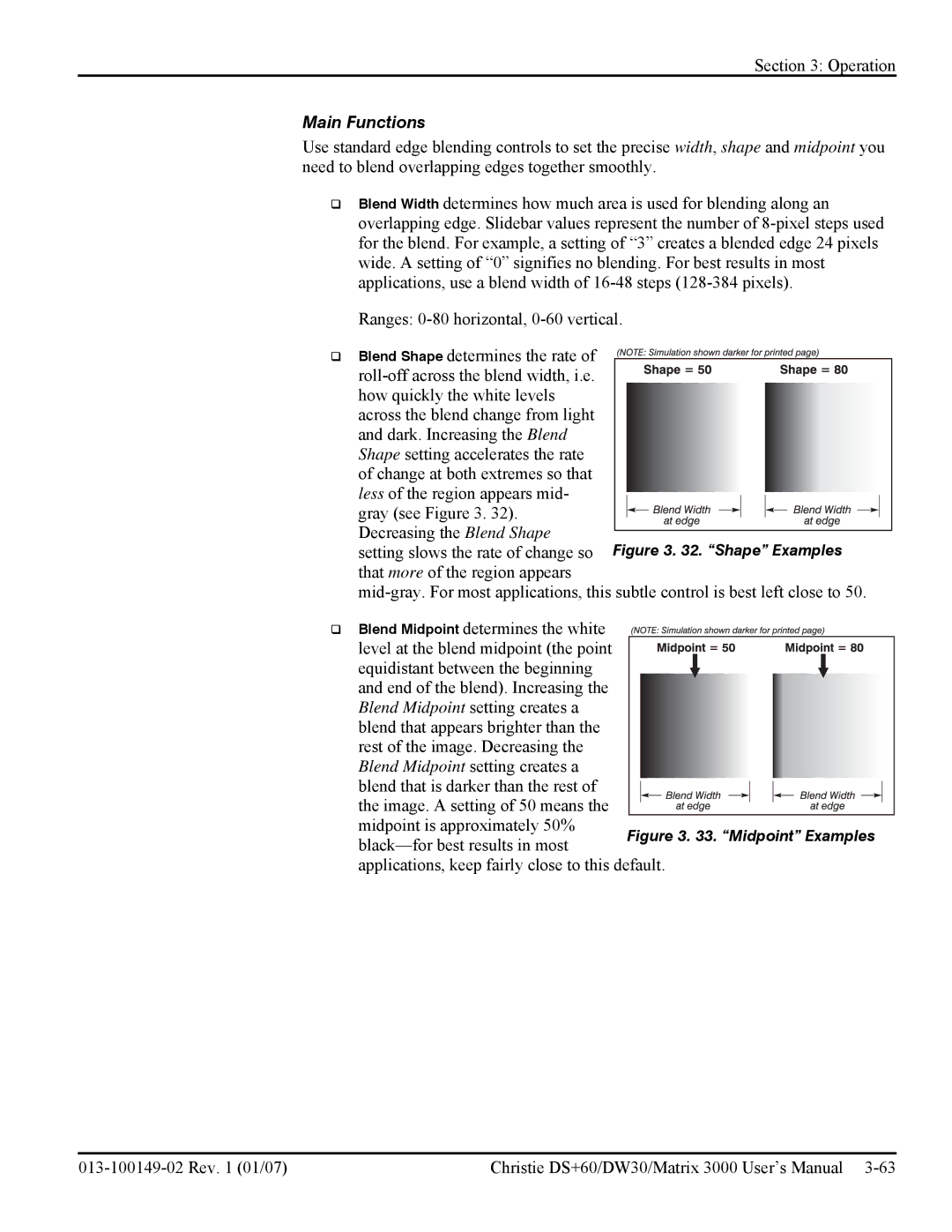
Blend Shape determines the rate of
across the blend change from light and dark. Increasing the Blend Shape setting accelerates the rate of change at both extremes so that less of the region appears mid-
gray (see Figure 3. 32). Decreasing the Blend Shape
setting slows the rate of change so that more of the region appears
Blend Midpoint determines the white level at the blend midpoint (the point equidistant between the beginning and end of the blend). Increasing the
Blend Midpoint setting creates a blend that appears brighter than the rest of the image. Decreasing the Blend Midpoint setting creates a blend that is darker than the rest of
the image. A setting of 50 means the midpoint is approximately 50%
applications, keep fairly close to this default.
Christie DS+60/DW30/Matrix 3000 User’s Manual |