Section 3: Operation
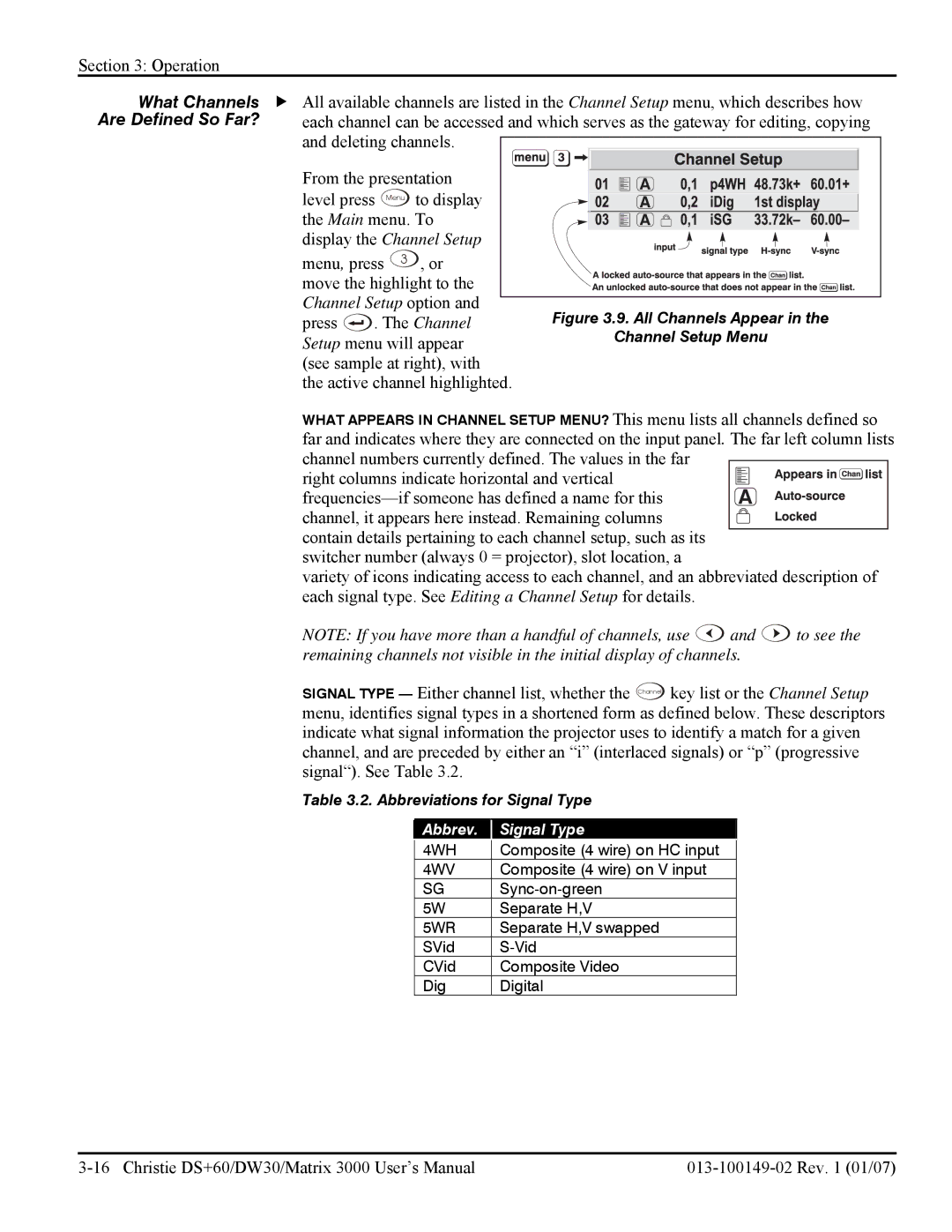
What Channels | f All available channels are listed in the Channel Setup menu, which describes how |
Are Defined So Far? | each channel can be accessed and which serves as the gateway for editing, copying |
| and deleting channels. |
| From the presentation |
| level press Menu to display |
| the Main menu. To |
| display the Channel Setup |
menu, press 3 , or move the highlight to the Channel Setup option and
press ![]() . The Channel Setup menu will appear (see sample at right), with the active channel highlighted.
. The Channel Setup menu will appear (see sample at right), with the active channel highlighted.
Figure 3.9. All Channels Appear in the
Channel Setup Menu
WHAT APPEARS IN CHANNEL SETUP MENU? This menu lists all channels defined so far and indicates where they are connected on the input panel. The far left column lists channel numbers currently defined. The values in the far
right columns indicate horizontal and vertical
switcher number (always 0 = projector), slot location, a
variety of icons indicating access to each channel, and an abbreviated description of each signal type. See Editing a Channel Setup for details.
NOTE: If you have more than a handful of channels, use ![]() and
and ![]() to see the remaining channels not visible in the initial display of channels.
to see the remaining channels not visible in the initial display of channels.
SIGNAL TYPE — Either channel list, whether the Channel key list or the Channel Setup menu, identifies signal types in a shortened form as defined below. These descriptors indicate what signal information the projector uses to identify a match for a given channel, and are preceded by either an “i” (interlaced signals) or “p” (progressive signal“). See Table 3.2.
Table 3.2. Abbreviations for Signal Type
Abbrev. |
| Signal Type |
4WH |
| Composite (4 wire) on HC input |
4WV |
| Composite (4 wire) on V input |
SG |
| |
5W |
| Separate H,V |
5WR |
| Separate H,V swapped |
SVid |
| |
CVid |
| Composite Video |
Dig |
| Digital |